

 Thanks:
  Likes:
  Needs Pictures: 0
 Picture(s) thanks:
Results 1 to 15 of 17
Thread: Harvey (?) Dividing Head
-
16th Nov 2020, 08:04 PM #1
 Golden Member


- Join Date
- Apr 2019
- Location
- Adelaide
- Posts
- 596
 Harvey (?) Dividing Head
Just looked at my dividing head and the cursive name tag seems to read Harvey. Has anybody heard of this brand?
It has a 40:1 ratio. It appears that the chuck should rotate up and down. There is a bevel gear just behind the crank handle that I assume means it is a universal head (and capable of doing helix gears)?
The one plate I have has the following hole patterns;
117
99
91
81
69
57
51
48
43
41
30
20201116_192658.jpg20201116_192552.jpg20201116_192543.jpg20201116_192530.jpg20201116_192518.jpg
-
16th Nov 2020, 09:52 PM #2
 Gear expert in training
- Join Date
- Aug 2008
- Location
- Melbourne
- Age
- 34
- Posts
- 1,080
I could well be wrong, but I was under the impression that universal dividing heads had a series of spur gears that could either be used "self contained" to divide finer than the plates allow or connected to a gear on the end of the table leadscrew for helical milling.
That doesn't look like a proper universal to me, but perhaps it's missing something.
-
16th Nov 2020, 09:57 PM #3
Philomath in training
- Join Date
- Oct 2011
- Location
- Norwood-ish, Adelaide
- Age
- 59
- Posts
- 6,561
I'd agree. A universal usually has a shaft sticking out the back to drive or be driven.
Michael
-
16th Nov 2020, 10:03 PM #4
Most Valued Member
- Join Date
- Jul 2016
- Location
- Melbourne
- Age
- 35
- Posts
- 1,522
Its an interesting design, I like the canted sector section. Looks American to me and I agree that the writing reads as Harvey.
Sent from my SM-G973F using Tapatalk
-
16th Nov 2020, 10:08 PM #5
Gear expert in training
- Join Date
- Aug 2008
- Location
- Melbourne
- Age
- 34
- Posts
- 1,080
We have one the same style at work, certainly more user friendly that way.
-
16th Nov 2020, 11:28 PM #6
Most Valued Member
- Join Date
- Sep 2012
- Location
- York, North Yorkshire UK
- Posts
- 6,477
These people made a lot of war issue machines and tooling. I can't find a legend the same as yours but probably the same people. Originally Posted by Mk1_Oz

G & A Harvey Machine ToolsBest Regards:
Baron J.
-
17th Nov 2020, 05:46 PM #7
Gear expert in training
- Join Date
- Aug 2008
- Location
- Melbourne
- Age
- 34
- Posts
- 1,080
Had a look at the one at work and it would seem we're both right; it is a universal and it is missing something.
PXL_20201117_020315865.jpgPXL_20201117_020321766.jpg
-
17th Nov 2020, 09:08 PM #8
Golden Member
- Join Date
- Apr 2019
- Location
- Adelaide
- Posts
- 596
Name your price!!! lol Originally Posted by elanjacobs
That extra casting does not look overly complex to recreate. Plain bearings? How does the shaft connect to the table screw? Do you have a 127 hole plate? Mine only came with the above single plate - not sure if that is all that was offered or if a 127 might be out there. Failing that I will prob have to ask somebody with a CNC mill to make me one.
Reading up on dividing heads today, it appears that a universal DH rotates the index plate to enable an almost infinite number of divisions. How would this Harvey be achieving that? It would appear that the missing shaft will rotate the chuck as the cut occurs forming a helix but can it also rotate the plate?
-
17th Nov 2020, 09:16 PM #9
I break stuff...
- Join Date
- Aug 2010
- Location
- Toorloo Arm, VIC
- Age
- 39
- Posts
- 1,297
No DRO on the mill, I take it? I'd just draw it up in CAD, and dimension all the co-ordinates off the centre hole, then plug away via the DRO. Someone with a DRO built any time after Noah sailed his ark could probably just do it with the inbuilt circular pattern feature.... Originally Posted by Mk1_Oz
Maybe a bit more scope creep is required - DRO's definitely ARE awesome on a mill, isn't it time you fitted one anyway?
-
17th Nov 2020, 09:30 PM #10
Golden Member
- Join Date
- Apr 2019
- Location
- Adelaide
- Posts
- 596
I am all modern like and have an Acurite II fitted to the Bridgeport! Looks like it is at least as old as the mill (Adcock & Shipley: Textron so sometime after 1968) and I do not think it has a luxury such as a circular pattern feature. I did think about doing exactly as you say but not being too sure about the amount of wear in the machine I thought twice. Suppose the 90:1 ratio makes any error even smaller so why not..... Originally Posted by Jekyll and Hyde
-
17th Nov 2020, 09:36 PM #11
Gear expert in training
- Join Date
- Aug 2008
- Location
- Melbourne
- Age
- 34
- Posts
- 1,080
Honestly no idea how this particular one works, the general setup for helical milling is like this
img22.jpg
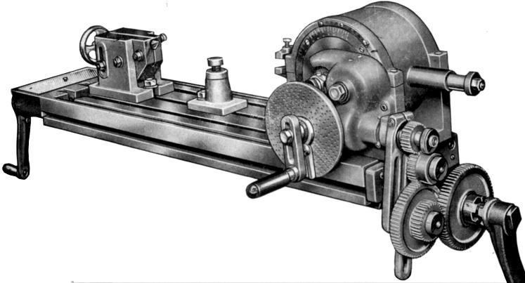
Maybe our heads can do helical milling but not differential indexing I doubt that functionality is even used because we have proper hobbing machines and CNC mills to do all that stuff
I can check the plates but I doubt there's a 127. They're not for sale anyway
There's about 500 bolt circle calculators on google so just punch in your numbers and print the result, much easier than drawing and dimensioning it. Wear in your mill shouldn't affect the DRO's accuracy; the scales just measure table movement, not leadscrew rotations, so backlash doesn't matter there.
-
17th Nov 2020, 10:18 PM #12
I break stuff...
- Join Date
- Aug 2010
- Location
- Toorloo Arm, VIC
- Age
- 39
- Posts
- 1,297
The answer to the 'missing bits' question appears to be in this post on another forum:
https://bbs.homeshopmachinist.net/fo...ing#post248476
And how it works seems to be explained more here:
https://www.youtube.com/watch?v=tQBhHjNO69s
If you thought your original change gear thread was bad though, you may not want to look... lol. I'm a bit scattered tonight, so I didn't manage to get very far without my eyes glazing over, but I'm pretty sure it explains it all.
I actually got to that trying to figure out how the 127 hole plate was actually going to work once you factor in the ratio of the dividing head or rotary table - then after finding the above, I found the answer I was actually looking for in the Engineers Black Book sitting on my desk...
-
18th Nov 2020, 11:25 PM #13
Golden Member
- Join Date
- Apr 2019
- Location
- Adelaide
- Posts
- 596
nice find will look tomorrow.
127 hole plate means 40 holes per tooth on a 40:1 DH if I understand things correctly
-
19th Nov 2020, 12:27 AM #14
Most Valued Member
- Join Date
- Sep 2012
- Location
- York, North Yorkshire UK
- Posts
- 6,477
Hi Guys,
I've had a warning pop up on this thread telling me that the page is insecure (pictures) nothing else I'm afraid.Best Regards:
Baron J.
-
19th Nov 2020, 07:57 AM #15
Philomath in training
- Join Date
- Oct 2011
- Location
- Norwood-ish, Adelaide
- Age
- 59
- Posts
- 6,561
See
https://metalworkforums.com/f65/t199...ntial-indexing
To get a universal dividing head cutting helical gears, the rear shaft is connected to the table feed so that as the table feeds, the dividing head rotates. Gearing is changed to alter the angle of helix. This is what is shown in the picture Elan posted in post 11.
For differential indexing, that shaft is connected via gears to the DH spindle, so that as the DH is rotated to the next position, the spindle via the gearing rotates the index plate slightly for all those intermediate tooth counts.
Michael

 Reply With Quote
Similar Threads
-
Help ID this dividing head
By OxxAndBert in forum METALWORK GENERALReplies: 7Last Post: 23rd Aug 2020, 03:42 PM -
Indexing head or dividing head?
By stevee7270 in forum METALWORK GENERALReplies: 16Last Post: 16th May 2016, 03:13 PM -
Indexing head or dividing head?
By stevee7270 in forum METALWORK GENERALReplies: 1Last Post: 26th Apr 2016, 04:34 PM -
dividing plates, dividing head
By eskimo in forum METALWORK GENERALReplies: 22Last Post: 4th Aug 2012, 06:17 PM -
dividing head
By tanii51 in forum METALWORK GENERALReplies: 9Last Post: 18th Oct 2010, 09:32 AM
