

 Thanks:
  Likes:
  Needs Pictures: 0
 Picture(s) thanks:
Results 1 to 7 of 7
-
30th Jun 2019, 07:05 PM #1
 Gear expert in training


- Join Date
- Aug 2008
- Location
- Melbourne
- Age
- 34
- Posts
- 1,080
 What's going on inside a 3-point bore mic
Found some old posters lying around at trade school and was told I could have them. There's a few on metrology (all the various limits and methods of measurement for specific features/tolerances) and this one, which is a labelled cutaway of a TESA Tri-o-bor.
IMAG3554.jpg
Dozens of parts and yet they still have a 2 micron resolution and +/- 4 micron tolerance, I can't imagine what the manufacturing tolerances must be to achieve that. Makes you realise why they start around $1500 each
-
30th Jun 2019, 07:26 PM #2
Philomath in training
- Join Date
- Oct 2011
- Location
- Norwood-ish, Adelaide
- Age
- 59
- Posts
- 6,561
Thanks for that.
While there are dozens of parts, the important bit is the cone against the sliding bits. Always wondered how they did that (balls was another possibility).
Michael
-
30th Jun 2019, 07:34 PM #3
Gear expert in training
- Join Date
- Aug 2008
- Location
- Melbourne
- Age
- 34
- Posts
- 1,080
That's just one way they do it, their Imicro goes one step further and actually has a threaded cone

-
30th Jun 2019, 08:54 PM #4
Most Valued Member
- Join Date
- Sep 2012
- Location
- York, North Yorkshire UK
- Posts
- 6,480
Hi Guys,
I've seen something similar that uses four steel balls and a micrometer type head.
Also a DIY version that uses three steel balls with two at 180 degrees apart and one in between pushing them apart, again using a commercial micrometer head. I'm sure that this one is on the web somewhere.Best Regards:
Baron J.
-
1st Jul 2019, 10:44 AM #5
Most Valued Member
- Join Date
- Jul 2016
- Location
- Melbourne
- Age
- 35
- Posts
- 1,522
I have a set of the bowers three point mics, very similar in design to the first style, but a bit simpler (they dont have that whole geared section in the thimble which i assume is there to provide more reduction/sensitivity?). the real advantage of the first style is you can get right to the bottom of blind holes.
Also setting up to grind that cone/helix must have been so much fun!
-
1st Jul 2019, 09:54 PM #6
Gear expert in training
- Join Date
- Aug 2008
- Location
- Melbourne
- Age
- 34
- Posts
- 1,080
I've been trying to wrap my head around this concept and I keep stumbling on what seems to me to be an obvious problem; the rate of outwards motion of the pushed balls is not going to be consistent across the downward travel of the pushing ball, so how can you directly read an accurate measurement on a standard mic head? Am I missing something obvious here? Originally Posted by BaronJ


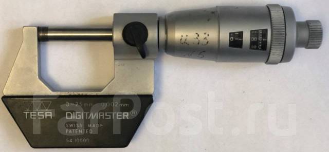
I believe the geared section in the head is purely for the readout; it's "digital" but displayed on 2 revolving cylinders, much like a car odometer. They used the same mechanism on the Digitmaster mics; the left window is 1mm/div and geared to the spindle, the right window is 0.002mm/div and directly attached. Originally Posted by caskwarrior
As for setting up to grind the cone, I'm sure it's all just drawn in cad and done on a cnc grinder. It probably could be done manually in a universal indexing head, but you'd need a machine that could geartrain the X and Z axes plus the rotary head together.
-
2nd Jul 2019, 02:56 AM #7
Most Valued Member
- Join Date
- Sep 2012
- Location
- York, North Yorkshire UK
- Posts
- 6,480
Hi Elanjacobs, Originally Posted by elanjacobs
I've never actually given it any thought.
They are both designs that I've come across on the net at some time. I particularly remembered the three ball one because it looked comparatively easy to build and it used a standard micrometer head, which are quite cheap and easy to find.Best Regards:
Baron J.

 Reply With Quote
Similar Threads
-
How did I bore a taper?
By StrayAlien in forum METALWORK GENERALReplies: 22Last Post: 9th May 2019, 09:30 PM -
Pulley bore enlargment
By BobL in forum METALWORK GENERALReplies: 11Last Post: 12th Jul 2016, 09:05 PM -
Locating a bore
By Michael G in forum METALWORK GENERALReplies: 24Last Post: 8th Jun 2015, 10:50 PM -
How to bore this tool holder?
By jack620 in forum METALWORK GENERALReplies: 38Last Post: 1st May 2013, 02:28 PM -
Bore gauges
By morrisman in forum METALWORK GENERALReplies: 58Last Post: 7th Jul 2012, 01:07 AM
