

 Thanks:
  Likes:
  Needs Pictures: 0
 Picture(s) thanks: 0
Results 1 to 15 of 44
-
28th Mar 2015, 08:41 PM #1
 Novice


- Join Date
- Jan 2005
- Location
- Brisbane
- Age
- 51
- Posts
- 19
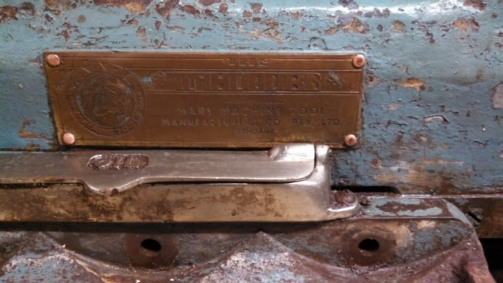
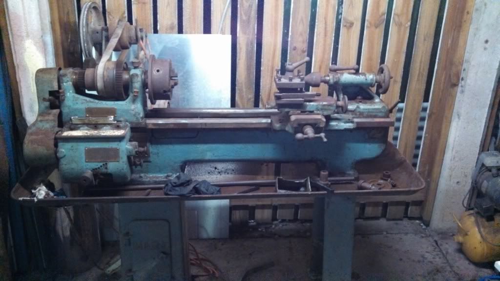
 Another MARS lathe. Model Unknown.
Hi All,
As promised from my welcome thread, some pics of the MARS lathe.
I will take a heap of photos during the process.
Hopefully it will provide some reference material to others wanting to know how these go together once I've sorted it out.
I got it home and into the shed today.
I've started to look at the condition of it, but haven't had too much time to digest or figure out exactly what will be required to get it running to a reasonable standard.
My difficulty is that the previous owners received the lathe in bits and put it together (loosely).
So I don't know what is missing, or if he has assembled it correctly.
First thoughts:
1) Needs a good clean (obviously).
mars lathe (Small).jpg
2) I was told the powerfeed didn't work. I can see a final gear in the gearbox with a missing tooth and some mig tack welds.
I have yet to sit down and work out if that gear is long enough, original, needs to be welded there, and how that drives the powerfeed shaft and/or the leadscrew.
It looks to me like the gear needs to be longer to take up the rest of the length of the shaft. Then it won't need to be tak welded, and would engaged both of the gears driving the powerfeed and lead screw.
The gears attached to the end of the leadscrew and drive shaft are not spaced/shimmed correctly at all and the castellated nuts are at the end of the available thread.
If anyone with a similar machine (I know there aren't many around) could give me an idea or a photo of what should be there, I would greatly appreciate it.
gearbox (Small).jpgspot weld (Small).jpgdrive shaft (Small).jpg
3) Back gears are missing completely, hence I will only have the 3 speeds at the moment.
Bull gear is missing teeth anyway.
I may get a reduction using swappable/reduction pulleys from the electric motor when I get one.
4) There is a second gear on the outside end of the gearbox (lowest gears at the geartrain end of the lathe in the photo) that doesn't seem to be used for anything.
Any ideas what this is for? I'm not sure it's supposed to be there.
gear train (Small).jpg
5) A fair amount of backlash exists in most places to my completely untrained eye.
Have yet to measure or work out if there is any way to adjust any of it.
I'm looking forward to working out more of the puzzle and cleaning pieces up tomorrow.
I have Thing1 (13 years old) and Thing2 (7 years old) giving me a hand.
Other pics....
back of apron (Small).jpgtop of apron (Small).jpgways (Small).jpg
-
28th Mar 2015, 08:59 PM #2
Pink 10EE owner
- Join Date
- Aug 2008
- Location
- near Rockhampton
- Posts
- 6,218
Looks like a handy bit of gear...
Amazes me what used to get made in Brisbane or indeed Qld and now isn't..Gold, the colour of choice for the discerning person.
-
28th Mar 2015, 09:19 PM #3
Most Valued Member
- Join Date
- May 2011
- Location
- Murray Bridge S Aust.
- Age
- 71
- Posts
- 5,959
Welcome to the forum. Looks like you've got a bit of work there, what is that stuff inside the apron, sawdust? I'm sure that you'll get plenty of help with information on the lathe. Looking forward to seeing the WIP reports.
Kryn
-
28th Mar 2015, 10:04 PM #4
Blacksmith, Cabinetmaker, Machinist, Messmaker
- Join Date
- Dec 2011
- Location
- Canberra
- Age
- 40
- Posts
- 4,515
Hi Scott,
Interesting Mars, i have never seen one like that, it looks to share parts with the Great Scott but the QCGB, saddle and apron are very different.
I'd say the feed/lead screw gears are supposed to be like that, the gear that has been welded on in the QCGB has a yoke on it so it can be slid to engage with one or the other.
The single biggest issue you have IMHO is not having the back gear, the flat belt drive really need the extra torque that the backgear gives.
Cheers,
Ew1915 17"x50" LeBlond heavy duty Lathe, 24" Queen city shaper, 1970's G Vernier FV.3.TO Universal Mill, 1958 Blohm HFS 6 surface grinder, 1942 Rivett 715 Lathe, 14"x40" Antrac Lathe, Startrite H225 Bandsaw, 1949 Hercus Camelback Drill press, 1947 Holbrook C10 Lathe.
-
30th Mar 2015, 12:00 PM #5
Novice
- Join Date
- Jan 2005
- Location
- Brisbane
- Age
- 51
- Posts
- 19
Thanks Gents,
Kryn, that's sawdust. There will be a lot of cleaning involved in this one.
Ew, I figure the same re: the back gears. But there isn't any shaft etc at all present.
I have a mate who is a genius with electrics, and I'll probably replace the motor with a VFD.
He's going to come and have a look on Wednesday.
With a 1400RPM motor and allowing the VFD to do 25% to 115% of rated motor speed, that should give me a range of around 80-1300 RPM at the chuck.
That's using the lowest an highest of the 3 belt driven gears.
Also, I have lubricated and got the broken gear sliding and selecting correctly and got the powerfeed and lead screw turning.
Now to get the gear fixed. everything else looks to be in working order.
I've read onthebeachalone's Mars Atlas lathe thread regarding his back gears, and there are pictures of the identical QCGB on it.
But he didn't have any stripped teeth, so I guess he didn't have to remove the shaft.
I'm looking at doing that now, so I can try and source another one or get one made while I continue the clean up.
(I'd try it myself but I don't have a working lathe )
Pictures are attached.
I can't see how to remove it without some major hassle.
There are no retaining grooves/pins etc that I can see.
I thought maybe the smallest gear was pinned, but I've been able to move it 5mm each way with judicious use of heat.
The centre wall in the casting does not go through, so I can't punch/press it out.
I assume the keyway goes all the way through, and the gears were pressed on in situ.
I can apply heat if required, but I can't see how to actually hold the shaft to withdraw it with the force required.
I thought I could make a "puller" using the hole in the shaft, but it doesn't seem to be threaded.
The hole in the shaft goes as deep as the selector collar.
Before I go do something stupid, anyone got any ideas?
I could heat it, then put cold spray down the centre of the shaft to quickly cool the shaft, but that might crack something?
Thanks,
Scott.
gearbox 1.jpggearbox 2.jpg
-
30th Mar 2015, 12:34 PM #6
Novice
- Join Date
- Jan 2005
- Location
- Brisbane
- Age
- 51
- Posts
- 19
OK. Thinking this through a bit more.
If there is a keyway, I can't see why the gears would have been pressed on.
With the amount of stuff missing on the lathe, just because the smallest gear on the cluster doesn't have a pin, doesn't mean one shouldn't be there. And it would locate the cluster.
The 2 threaded holes in the casting either side on the shaft would then mean a cover plate to retain the shaft.
So I've used some heat sparingly to move the pinned gear again and lubed.
It now moves freely up and down the shaft. There are holes for a pin in the shaft, but I haven't gotten as far as ensuring they go all the way through to allow for later pin removal.
There was a fair amount of crud (technical term) from old dry oil buildup under the gear. Some of the others are starting to loosen. I suspect I'll have the shaft out soon as long as I go softly, softly....
-
30th Mar 2015, 12:40 PM #7
Senior Member
- Join Date
- Nov 2013
- Location
- Brisbane
- Posts
- 102
I *think* its the same as mine - a Thor.
Plate at the headstock should say.
Mine's minus the Apron in this photo:
I'm missing the support for the power feed at the tailstock end on mine, and a couple of gears in the apron - would be good to come visit and take some measurements/photos.
-
30th Mar 2015, 12:47 PM #8
Senior Member
- Join Date
- Nov 2013
- Location
- Brisbane
- Posts
- 102
Oh, and the second gear that's doing nothing on your cascade is there as a different set of ratios - swap it out for the gear that is engaged, and you'll probably have a selection of metric feeds - I also have a spare gear, but it's not mounted like yours.
-
30th Mar 2015, 12:51 PM #9
Novice
- Join Date
- Jan 2005
- Location
- Brisbane
- Age
- 51
- Posts
- 19
Hi Gamma,
That Thor looks very similar if not the same.
Doesn't have the "Thor" on the nameplate though.
Sure, PM me. You are welcome any time.
Once you've got the info and measurements to make the parts, I'm sure you'll be up and running in no time. It's finding the reference with these that is hard.
I've got the apron etc all sitting there ready to be cleaned up, so access is easy.
Take as many photos and measurements as you want.
The PF support at the tailstock end locates on a pin behind the crossfeed rack as well as the bolts.
Would you mind taking a photo of the tailstock end of your gearbox for me, so I can check if there is supposed to be a cover plate retaining the shaft?
Gears on mine are starting to loosen up now.
Cheers,
Scott.
-
30th Mar 2015, 02:04 PM #10
Senior Member
- Join Date
- Nov 2013
- Location
- Brisbane
- Posts
- 102
Thanks. Will take a pic tonight - I have to pull the lube feed from the spindle cap and measure the threads tonight anyway. Originally Posted by hudnut

-
30th Mar 2015, 06:43 PM #11
Novice
- Join Date
- Jan 2005
- Location
- Brisbane
- Age
- 51
- Posts
- 19
Got the gears off.
It took some effort of gently coaxing and getting the gears unstuck.
Also turns out that it isn't a blind hole in the casting, so I could punch it out.
However, the gears were well and truly stuck, so I had to loosen them up anyway.
Looks to me that when the shaft was installed the gears were tight, and the shaft was hammered.
The end of the shaft has been "belled".
There is some scoring and the key isn't in good shape.
So I think I am up for some linishing, cleaning up some minor burrs on gear teeth, a pin, and possibly an endplate.
Oh, and I've got to get the selector gear fixed.
Any ideas on where in Brisbane I could get another made up?
I assume a whole new one piece rather then just another sleeving like the previous attempt would be in order.
I don't know how much that would cost either.
leadscrew-powerfeed-selector-1.jpgleadscrew-powerfeed-selector-2.jpglathe gears.jpg
-
30th Mar 2015, 07:46 PM #12
Philomath in training
- Join Date
- Oct 2011
- Location
- Norwood-ish, Adelaide
- Age
- 59
- Posts
- 6,561
A complete unit would be preferable. Looking at the photos in post 5 the selector gear does not look to be the same proportions as the other gears so I suspect that it was a ring-in. I was just saying in another thread that machine makers having individual ideas about their machines means making your own gears is sometime essential. Commercially to get something like that made I suspect you would be up for several hundred. If no one closer volunteers I could probably make a reasonable copy for you but you would need to post it to me here in Adelaide so I could measure it up. Originally Posted by hudnut
Michael
-
30th Mar 2015, 07:55 PM #13
Blacksmith, Cabinetmaker, Machinist, Messmaker
- Join Date
- Dec 2011
- Location
- Canberra
- Age
- 40
- Posts
- 4,515
If it is the same as my Mars it will be 14DP, not a real common size.
1915 17"x50" LeBlond heavy duty Lathe, 24" Queen city shaper, 1970's G Vernier FV.3.TO Universal Mill, 1958 Blohm HFS 6 surface grinder, 1942 Rivett 715 Lathe, 14"x40" Antrac Lathe, Startrite H225 Bandsaw, 1949 Hercus Camelback Drill press, 1947 Holbrook C10 Lathe.
-
30th Mar 2015, 08:39 PM #14
Philomath in training
- Join Date
- Oct 2011
- Location
- Norwood-ish, Adelaide
- Age
- 59
- Posts
- 6,561
I have 14DP down to 20t (darn!)
The current selector gear has 18t and looks to be around 12DP - it certainly looks beaten up, so measurement of the mating gear may be in order to see what it should be (I suspect that it is not the same DP, hence the broken tooth and chewed up appearance). The other gears in the cluster look to be smaller still - maybe 18DP? Hard to say without proper measurements.
Regardless of that I'm sure that the combined might of the forum can work something out...
Michael
(Hudnut - can you do a tooth count and measure the OD of the mating gear. How good does it look?)
-
30th Mar 2015, 10:53 PM #15
Novice
- Join Date
- Jan 2005
- Location
- Brisbane
- Age
- 51
- Posts
- 19
Thanks Michael,
I've attached some photos. Bad lighting though I'm afraid.
The leadscrew gear has some teeth wear on one face.
I'm going to be doing some tooth cleanup in a number of places.
Previous owner obviously had some issues engaging it I'd say.
Probably due to bad meshing as you mention, and I don't think the gears were spaced correctly on the leadscrew either.
Meshing of leadscrew gear and selector gear is not good.
Meshing of leadscrew and powerfeed gears is better, but not perfect. Maybe due to the state of the gears.
I'm not across a lot of the gear making stuff yet.
I'm in the middle of reading up on DP etc, and don't have the practical exposure to see different profiles yet.
I intend to be able to make my own (and for others) eventually, but I obviously need a machine, tooling and some experience first.
Apart from that, I'm all over it.
I'm going to be talking in a mix of metric and imperial here.
Leadscrew - Just over 36mm OD, more like 1 7/16 inch, 18 teeth, stamped with "M18S", ID 19mm
Powerfeed - 47mm OD, 24 teeth, ID 16mm
Selector gear - measured in a number of places due to variance and high bodge rating. Ranges from 36mm to 1 7/16 inch OD, 18 teeth (now 17), ID of sleeve 19mm (diameter of shaft)
Top 2 gears in the first photo are largest and smallest gears from the cluster.
Bottom row in first photo left to right are selector gear, powerfeed shaft gear, leadscrew gear.
gear selection.jpgleadscrew gear.jpgpowerfeed gear.jpgselector gear.jpg

 Reply With Quote
Similar Threads
-
Mars lathe
By Ueee in forum EBAY, GUMTREE, and other off forum sales sitesReplies: 8Last Post: 15th Mar 2017, 09:06 PM -
Mars bar no, Mars lathe!
By neksmerj in forum METALWORK GENERALReplies: 20Last Post: 29th Sep 2012, 08:18 PM
