

 Thanks:
  Likes:
  Needs Pictures:
  Picture(s) thanks:
Results 1 to 15 of 75
-
19th Feb 2013, 04:12 AM #1
 Golden Member


- Join Date
- Oct 2012
- Location
- Australia
- Posts
- 621
 XinXing Measuring Tools Factory Granite Surface Plate Vs HP Laser Interferometer
I have been meaning to test the Grade 0 610mm x 914mm XinXing Measuring Tools Factory granite surface plate that was part of the group buy. I had the laser interferometer set up to test something else so I thought while it is setup while not have a quick survey of the plate and see how it matched up with the calibration sheet. of me testing one of the diagonals The second half of the video is is the same as the first but I put the camera where you can see the display more clearly. All the measurements are in millimetres.
I also tested the other diagonal and along the center lines and here is what I got
Diagonal 1. Seen in video ~2.4 microns (very good in the centre, but with a drop off at the comers.
Diagonal 2. 1.9 micron with a 0.2 micro dip about a third of the way in
Long axis was good , if I ignore the last 50mm of the plate it is 1.8 micron with the last 50mm it is 2.8
Short axis was more of the same at 2.2 microns with a couple of dips.
Long Axis was up an down here are the numbers starting at 100mm from the edge and was the most interesting.
100 +0.00007mm
150 -0.00012mm
200 -0.00045mm
250 -0.00007mm
300 +0.00035mm
350 -0.00018mm
400 +0.00028mm
450 +0.00004mm
500 +0.00045mm
550 +0.00056mm
600 +0.00045mm
650 +0.00063mm
700 +0.00084mm
750 +0.00115mm
800 +0.00136mm
850 -0.00147mm
The thing to note here is that the centre is very very good, but very bad at the edges
here is a crude graph.
Long Center line.jpg
With this quick measuring done (actually long a tedious process of aligning mirrors for the laser) it is time to compare with the supplied calibration sheet. And as the plate is mounted at the moment I would have to say that the calibration sheet is bogus. according to the sheet the plate should be much worse than it is. It is at least twice as good as the supplied inspection sheet says with a 4.3 micron deviation. The main one that gets me is should be a ~3 micron drop on the diagonals according to the sheet but in reality it is more like 0.5-1 micron drop.
So in summary use your XinXing Measuring Tools Factory granite surface plate with confidence, and stay away from the edges for the really important stuff.
-
19th Feb 2013, 11:34 AM #2
.
- Join Date
- Nov 2008
- Location
- Perth WA
- Age
- 71
- Posts
- 6,459
I'ts a great thing that that gear is in the hands of a couple of blokes that can use it. You bulk buy boys will all be breathing a sigh of relief.
BT
-
19th Feb 2013, 12:15 PM #3
Most Valued Member
- Join Date
- Jun 2008
- Location
- Victoria, Australia
- Age
- 74
- Posts
- 5,080
Been wondering why the actual measurements are so much better than the supplied calibration chart, and I can only guess at what QC procedures they use. Maybe we need to talk to inspector #1..

FWIW If you just worked with the middle 2/3d's of the plate it's well under 1/2 micron flatness..
So thanks Greg for organizing such precision surface plates I'd expect the others to be similar.
Regards
Ray
-
19th Feb 2013, 12:42 PM #4
Most Valued Member
- Join Date
- Jul 2010
- Location
- Melbourne
- Posts
- 9,088
Hi Josh,
Bearing in mind I know next to nothing about these things and am just looking at my report* and your video.
As you say and my report shows the plates drop off at the corners.**
Your numbers are showing the same thing but, are missing three of what will likely be the worst points 0, 50 and 900.
(as I dont have the numbers for the diagonal I'll use the numbers you gave as an e.g.)
If you add an error between 50 and 100 the same as the error between 800 and 850 things(-0.00283mm), wont look so good. Then I guess it comes down to how close to the corners they measure? Assume*** the drop off continues and that they can measure to the corners(?), you end up with this. though the diagonal you show doesnt look as bad as that.
Having said all that, thanks for the time and effort. Nice to know they arent a kitchen bench top.
One data point doesn't make a sample I'll clear the area around my plate for you
Stuart
*you say ~3 micron drop on the diagonals? isn't your center point the highest and two diagonally opposite corners the lowest(or zero if you like)? All the reposts I have seen(about 6) have two corners 0.0 and everthing else is +. Or do you mean "drop" from the center point?
**talking about the diagonals only as the other lines aren't fixed to anything without a lot of maths.
***a fairly large assumption (wow it took me over an hour to get one post typed lol)Last edited by Stustoys; 19th Feb 2013 at 12:51 PM. Reason: ***
-
19th Feb 2013, 12:43 PM #5
 Most Valued Member
- Join Date
- May 2011
- Location
- Murray Bridge S Aust.
- Age
- 71
- Posts
- 5,959
Probably the reason for the discrepancy, would be that the sheet is printed to the max. acceptable tolerance, so that if a few slip through that are close to the sheet specs no-one can complain!!!!!!!!!!
My thoughts anyway.
Kryn
-
19th Feb 2013, 02:21 PM #6
Golden Member
- Join Date
- Oct 2012
- Location
- Australia
- Posts
- 621
Kryn, you are probably right.
Stuart, they are definitely keepers. You are right I only have one datum point for this plate (at the the centre hence my phrase drop to the edge), and to do a true(best that is possible with the gear) re-certification of the plate I would have to use the small grid plate and mark off grid at ~50mm spacings and take double measurements both ways to get to the edge and account for the error (incidentally that is the way that HP outlines in their surface plate calibration guide). This yields buckets of data points that need to be meshed together, and I would really need the HP calculator up and running with the surface plate software connected to the plotter to do it without a brain melt down. However I was just after a comparison to the provided sheet and I think I could be wrong here but along any one line one data line on the calibration sheet I should be able to make a reasonable correlation to it. According to the sheet on both diagonals it should have gone from zero to ~3 microns in the centre and back down again to zero, it didn't on either diagonal the centre hump is kind of there but not to the same extent. In regards to the very edge I made an error in my marking off the distance. all the measurements for the distance from the reference edge should be + ~50mm so 850 is really 900. The drop off is even sharper than my data would suggest if I pulled back towards the center it back just 10mm the deviation would have been a micron less. So maybe its that the outside data points are just very close to the edge. I seem to remember reading the classification specification for surface plates at one stage and I think there was a border that does not count as the working surface and is meant to be exempt from contributing to the classification tolerance for flatness (I think is was one to two inch border?). Maybe nobody told XinXing about the working surface border and they have been measuring to the edge??? I know what its like reading techspecs day after day, I would hate to think what it would like in a different language.
Before I do any more plates I think I will get the procedure down first. I think that will be about a week after we finish off the trolley that said plate is meant to be on, not the rolling project bench that it is sitting on at the moment.
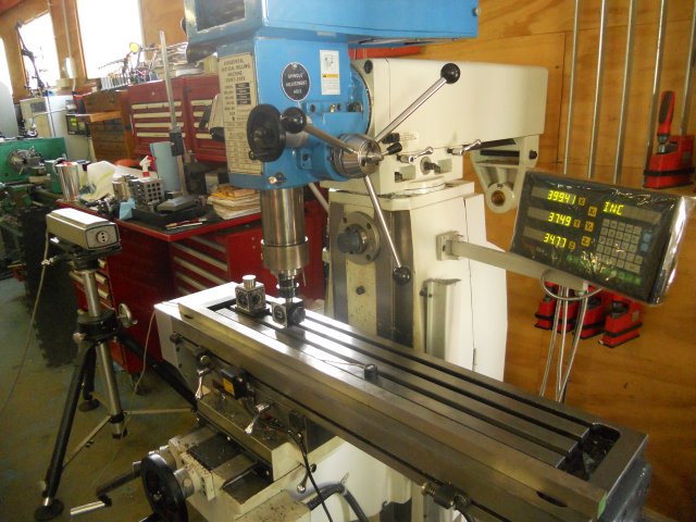
FYI you can use the same optics to a an insanely sensitive tram by mounting the retro reflectors in the quill, I did the x axis on the mill this morning and it was almost impossible to get it right, its like the whole mill is a flippy floppy indicator stand with a twitchy tenths gauge, but now it is within a couple of microns across the entire length of the table. I don't know why I bothered since the table is nowhere near that flat; end to end it is out ~70 microns. My next trick will be to test the accuracy of the DRO and square the X and Y.
 Originally Posted by Stustoys

-
19th Feb 2013, 02:35 PM #7
Member: Blue and white apron brigade
- Join Date
- Feb 2006
- Location
- Perth
- Posts
- 7,189
Good work on the measurements
How reproducible are the results? In other words if you repeat the sequence of measurements how well do they agree?
Another interesting test is does measuring the deviations going inwards from the edge give the same result as outwards from the centre?
-
19th Feb 2013, 06:43 PM #8
Most Valued Member
- Join Date
- Jun 2008
- Location
- Victoria, Australia
- Age
- 74
- Posts
- 5,080
Yep, testing the accuracy of the DRO is something I'm looking forward to.. Just how good are the optical scales? Originally Posted by Brobdingnagian
Hi Bob, Originally Posted by BobL
Josh can elaborate a bit more than me, but if you watch the video close up of the display , you'll see the starting point measures +0.07 microns, and when returned to starting position it's back to about the same.
So reproducibility within a shortish time period is in the +-0.01 micron range, but at that sort of level air currents and random temperature fluctuations can play havoc. The consistency and stability has been pretty good since fitting the automatic compensator, which measures air pressure/temperature and humidity as well as material temperature, then applies continuous corrections.
Regards
Ray
-
19th Feb 2013, 07:11 PM #9
Member: Blue and white apron brigade
- Join Date
- Feb 2006
- Location
- Perth
- Posts
- 7,189
NICE! Originally Posted by RayG
-
19th Feb 2013, 07:55 PM #10
Most Valued Member
- Join Date
- Jul 2010
- Location
- Melbourne
- Posts
- 9,088
Thanks Josh, got it now I think.
Maybe you guys have worn in down already
I wonder how much of that 70 microns is sag?
I tested my DRO against a 300mm vernier, I dont recall being overly impressed with the result so it will be interesting to see what you come up with. Some DROs can be adjusted for the scale as long as the error is consistent. Though not mine as far as I know.
Stuart
-
19th Feb 2013, 08:53 PM #11
Just some guy.
- Join Date
- Jul 2003
- Location
- The Fabulous Gold-plated Coast.
- Age
- 69
- Posts
- 2,251
Another data point...
I own an ancient Taylor Hobson Talyvel...an electronic differential level. I did a quick union jack survey of my plate to check the accuracy and the certificate. The plate was better than the cert, and the errors that I could detect were not in the same place as the chart*
Not that the chart is useful anyway, as the plate lacks a label anywhere. Typically the chart is supposed to reflect the plate's condition with the label facing the user.
Ayway, I too was happy to find my plate better than the cert, well within grade A. I wonder if they have a bunch of certs that are supplied randomly? I wanted to see if any of ours were duplicates but got distracted by the logisitics of the whole deal.
Greg QIt's all part of the service here at The House of Pain
-
19th Feb 2013, 11:04 PM #12
Golden Member
- Join Date
- Oct 2012
- Location
- Australia
- Posts
- 621
BobL,
Repeatability is good. Going both ways they agree to within 0.0005mm after that it is a little hit and miss, mainly due to the exact starting location and measuring point. If I had another laser,optics, automatic compensator duplexer and display I could get the position measurement accurate as well and bring those errors down. But with one setup repeatability is pretty good as can be seen in the video, but you have to hold your breath and not move at all, moving on the concrete around the the plate will move the reading in the x10 mode. I was reading in the pile of manuals for this thing today and found that there is resolution extender that will take it down even further to ludicrous sensitivity: ~3 angstroms or a little more than the diameter of an atom of iron. I presume the only time it could be usable is in a vacuum chamber.
Stuart,
At least half of the 70 microns is sag.
I did the X axis DRO comparison, and without knowing what the cosine error is, it is better than -0.18mm over 500mm or -0.0349mm in 100mm.
-
20th Feb 2013, 08:46 PM #13
Most Valued Member
- Join Date
- Jun 2008
- Location
- Victoria, Australia
- Age
- 74
- Posts
- 5,080
I Did a little more on the DRO accuracy, the setup is as per the way Josh had it already worked out, I just collected some more data, I was particularily interested in accuracy over shortish distances, like say 100mm
The table was run back and forwards at different speeds to see if the encoder was tracking sudden movement, and I think it's ok as far as pulse speed goes.
The other source of error would be the accuracy of the scale itself.. so I did some readings from 0 to 100mm and a few spot checks out to 400mm x axis travel
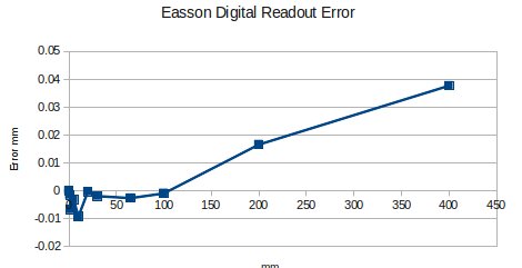
So DRO accuracy is pretty good over relative moves of 100mm or so, but longer measurements look less accurate.
Good know the money spent on DRO's isn't wasted..
Regards
Ray
-
20th Feb 2013, 09:22 PM #14
Blacksmith, Cabinetmaker, Machinist, Messmaker
- Join Date
- Dec 2011
- Location
- Canberra
- Age
- 40
- Posts
- 4,515
Good work Josh and Ray
I did wonder about the certs BT and i got with our carbatec plates, i'm pretty sure they are identical. It would be also interesting to see if a cheap set of gauge blocks measure what the cert says or not. I guess i could offer a few random ones up to test if you are interested.....
The DRO accuracy is also of interest, i wonder if the Easson DRO's are any better than the sinpo's/chfoic's? I am seriously thinking of one for Mlle but would like to see some data first......1915 17"x50" LeBlond heavy duty Lathe, 24" Queen city shaper, 1970's G Vernier FV.3.TO Universal Mill, 1958 Blohm HFS 6 surface grinder, 1942 Rivett 715 Lathe, 14"x40" Antrac Lathe, Startrite H225 Bandsaw, 1949 Hercus Camelback Drill press, 1947 Holbrook C10 Lathe.
-
20th Feb 2013, 09:50 PM #15
Most Valued Member
- Join Date
- Jul 2010
- Location
- Melbourne
- Posts
- 9,088
Hi Ray, Josh,
I have a feeling mine maybe worse than that. Rays numbers would put it on the limit of detection with a 300mm vernier. Joshs numbers would be below my limit of worry. Of course that assumes my Mitutoyo vernier is better than my DRO. I know which one I'd be betting on. Of course it could have been me. Mill is set up ATM. I'll try and check it again tomorrow.
How do you feel about getting up early and running the tests again when things have cooled off a little?
If its the aluminium that has the greatest effect on the scale?? 10C should do nicely
Stuart

 Reply With Quote


Similar Threads
-
Source of granite surface plate, squares etc
By Ueee in forum METALWORK GENERALReplies: 50Last Post: 13th Jul 2015, 10:26 AM -
SOLD: Granite surface plate grade A
By Greg Q in forum METALWORK - Machinery, Equipment, MARKETReplies: 8Last Post: 18th Jun 2012, 08:44 PM -
Layout ink on a granite surface plate
By markjaffa in forum METALWORK GENERALReplies: 10Last Post: 1st Nov 2010, 10:45 PM
