

 Thanks: 0
 Likes:
  Needs Pictures: 0
 Picture(s) thanks: 0
Results 46 to 60 of 308
Thread: Mars Lathe DC motor conversion.
-
2nd Oct 2012, 07:52 PM #46
 Most Valued Member


- Join Date
- Jun 2008
- Location
- Victoria, Australia
- Age
- 74
- Posts
- 5,080

Hi Ewan,
If it's only one winding, then I'd guess it's a choke, probably just for harmonic filtering.
Regards
Ray
-
2nd Oct 2012, 09:03 PM #47
Most Valued Member
- Join Date
- Aug 2011
- Location
- Melbourne
- Posts
- 4,779
I think they are in most Treadmills. I think it's an RF choke which helps reduce higher frequency noise on the line supply?
Simon
-
2nd Oct 2012, 09:10 PM #48
Most Valued Member
- Join Date
- Jul 2010
- Location
- Melbourne
- Posts
- 9,088
I imagine there would be a near riot at the gym if it interfered with an ipod!!!!

-
2nd Oct 2012, 09:11 PM #49
Blacksmith, Cabinetmaker, Machinist, Messmaker
- Join Date
- Dec 2011
- Location
- Canberra
- Age
- 40
- Posts
- 4,515
Makes sense i guess. There was no ferrite ring on the motor line with this one. It seems to be wired in on the DC side, but its hard to tell as a whole lot of stuff terminates into what looks to be a solid state relay. It also has no markings so it a bit hard to tell what it is doing and connecting to what. Plus its a double sided board so trying to trace things is a nightmare!
1915 17"x50" LeBlond heavy duty Lathe, 24" Queen city shaper, 1970's G Vernier FV.3.TO Universal Mill, 1958 Blohm HFS 6 surface grinder, 1942 Rivett 715 Lathe, 14"x40" Antrac Lathe, Startrite H225 Bandsaw, 1949 Hercus Camelback Drill press, 1947 Holbrook C10 Lathe.
-
2nd Oct 2012, 09:54 PM #50
Diamond Member
- Join Date
- Sep 2006
- Location
- Australind , WA
- Age
- 58
- Posts
- 1,281
 Originally Posted by Ueee

My guess is that its an Inductor or Choke (same thing )
-
5th Oct 2012, 09:47 PM #51
Blacksmith, Cabinetmaker, Machinist, Messmaker
- Join Date
- Dec 2011
- Location
- Canberra
- Age
- 40
- Posts
- 4,515
I ventured out today and picked up a few things from Jaycar and the KB power resistors for the controller. As soon as i got home i hooked the controller up to the motor and turned her on. Something seemed really wrong....the top speed was pitiful! After adjusting and fiddling i got the top speed up somewhat, but it still seemed a bit slow. I checked the out put voltage...220v what the? So i put the flywheel on the motor and set up the tacho to check.....well what a surprise i got! The motor was doing a touch over 6000 rpm....
 Wow its smooth! So i re-adjusted the settings to bring the speed down and i am very happy.
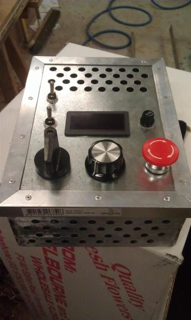
I then set about making a switch box for all the electronics. .6 gal with ally trim. Tried my hand at welding the corners with the mig....its ok if you don't look too hard....i'm still not used to the mig.
I have OFF/FWD/REV, speed knob, emergency cut off, AC fuse, tacho and switches for the motor cooling fan and to turn the brake on/off. Yikes! no wonder i couldn't find a big enough box at Jaycar.
 1915 17"x50" LeBlond heavy duty Lathe, 24" Queen city shaper, 1970's G Vernier FV.3.TO Universal Mill, 1958 Blohm HFS 6 surface grinder, 1942 Rivett 715 Lathe, 14"x40" Antrac Lathe, Startrite H225 Bandsaw, 1949 Hercus Camelback Drill press, 1947 Holbrook C10 Lathe.
-
5th Oct 2012, 10:18 PM #52
Most Valued Member
- Join Date
- Jun 2012
- Location
- SA
- Posts
- 1,649
Looks good Ewan.
I'm on the last stretch with my conversion as well.
Heavily into wiring up the system.
One more day may just do it.
I just hope this all works as planned.
Cheers
Rob
-
6th Oct 2012, 08:34 AM #53
Most Valued Member
- Join Date
- Aug 2011
- Location
- Melbourne
- Posts
- 4,779
Hi Ewan,
That's looking great! IRT motors and their smoothness, it never ceases to amaze me how smooth both the DC and 3 phase motors are compared to the regular single phase motor counterparts. I would love to have seen the look on your face when you read the optical RPM reading! 6000 RPM gives you a huge range and huge torque from wo to go!
The enclosure looks great. Not sure if you were going for the contemporary industrial look but I like it. Looks great!
Simon
-
6th Oct 2012, 01:28 PM #54
Most Valued Member
- Join Date
- Jun 2012
- Location
- SA
- Posts
- 1,649
I have my DC controller crammed into an old XT PC power supply case, with the tacho display mounted separately to suit with my Chinese lathe configuration, but seeing Ewan's metal box gave me an idea.
You could just buy one of those cheap rectangular $10 metal tool boxes Mitre 10 etc have and take off the handle and mount it vertically with the lid being the front. Hinges open nicely, add a few vent holes and presto great little controller box.
Save a lot of stuffing around making one.
Cheers
Rob
-
6th Oct 2012, 07:53 PM #55
Blacksmith, Cabinetmaker, Machinist, Messmaker
- Join Date
- Dec 2011
- Location
- Canberra
- Age
- 40
- Posts
- 4,515
That toolbox idea is great Rob, would have saved me some time.
Although the motor revs rather happily to 6k i will stop it at about 3k. All the higher speed will do is wear it out quickly. I will already have to re-gear my lathe about 2-1 to make up for the extra motor speed.
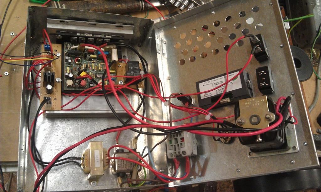
I filled the box up with most of the wiring today, i am just waiting on the braking resister and then i can hook up its relay etc, and clean up the wiring. It all works as it should, the motor can be switched on/off with the speed pot or the main switch, and it runs just as well in reverse as it does forwards. Mind you the only reversing i can see it doing will be for threading.
I am using a 7812 reg for the 12v controls and fan and although i have it on a small heatsink it is getting pretty hot with the fan running. My rectified DC voltage is up near 19v so its a bit high for the fan unregulated. I'll just have to wait and see, the 7812 should be good to 1 amp and the fan is only .65a so its got me .
.
On a totally different train of thought i have been thinking of my "perfect" PWM controller, and have been wondering if a MOSFET could be used instead of a relay to control the braking, giving PWM adjustable braking speeds......
 1915 17"x50" LeBlond heavy duty Lathe, 24" Queen city shaper, 1970's G Vernier FV.3.TO Universal Mill, 1958 Blohm HFS 6 surface grinder, 1942 Rivett 715 Lathe, 14"x40" Antrac Lathe, Startrite H225 Bandsaw, 1949 Hercus Camelback Drill press, 1947 Holbrook C10 Lathe.
-
6th Oct 2012, 09:04 PM #56
Most Valued Member
- Join Date
- Jun 2008
- Location
- Victoria, Australia
- Age
- 74
- Posts
- 5,080
Hi Ewan,
The 7812 will run hot with 19V input, You can calulate the dissipation as follows, (19-12) - 7 volts drop, 7 * 0.65 = 4.5 watts, heatsink looks like about 10C/watt, so you'd expect something like 45C above ambient?
A good choice is to chuck the 78xx series, and use one the more modern 3 pin SMPS like this one, R-78C12-1.0 Recom Power Inc | 945-1392-5-ND | DigiKey
They run cool and don't need a heatsink.
Looking at your wiring, I don't see any strain relief anywhere, but full marks for heatshrinking all the terminations
Whenever I run wiring to a hinged door, I run it as an "L" shaped loom with the vertical part of the "L" close to ( and parallel to ) the hinge line, that way you aren't flexing the wires when the door opens/closes.
Regards
Ray
-
6th Oct 2012, 09:17 PM #57
Most Valued Member
- Join Date
- Jun 2012
- Location
- SA
- Posts
- 1,649
Good to see your conversion is going well Ewan.
I wired mine up today, and I've hit a snag.
I'm not sure what's going on.
The motor starts up,and blows either the AC or DC fuse almost straight away.
I've checked the connections and they look OK, so I'm not sure if it's a bad controller or what.
I will run the multimeter over the output tomorrow and see what's happening.
I have another motor I can try as well. Will check the output voltage first.
Cheers
Rob
-
6th Oct 2012, 09:22 PM #58
Blacksmith, Cabinetmaker, Machinist, Messmaker
- Join Date
- Dec 2011
- Location
- Canberra
- Age
- 40
- Posts
- 4,515
Thanks Ray, i'll look into getting a few of those regs. 45deg sounds about right, although i didn't check it with anything but my fingers. Still need to anchor all of the wiring, i have plenty of length with most of it to do as you suggest. I have found in the past (the hard way) that the only way to makes sure a crimp fitting doesnt come loose is heatshrink, so thats why it is everywhere.....
1915 17"x50" LeBlond heavy duty Lathe, 24" Queen city shaper, 1970's G Vernier FV.3.TO Universal Mill, 1958 Blohm HFS 6 surface grinder, 1942 Rivett 715 Lathe, 14"x40" Antrac Lathe, Startrite H225 Bandsaw, 1949 Hercus Camelback Drill press, 1947 Holbrook C10 Lathe.
-
7th Oct 2012, 01:27 PM #59
Most Valued Member
- Join Date
- Jun 2012
- Location
- SA
- Posts
- 1,649
Well I've tracked down my problem with the DC lathe conversion.
I sure can pick them, the donor DC motor is stuffed - arcing inside at anything over about 5 amp.
So it's back to square one, do not pass GO and collect $200 - go directly to Jail.
Wouldn't it just give you the ####s?
I have another motor that I know works (1.5 HP) but I now have to rework the entire motor mount and fans to fit it.
I am more than slightly peeved at this point in time.
Cheers
Rob
-
7th Oct 2012, 03:08 PM #60
Most Valued Member
- Join Date
- Aug 2011
- Location
- Melbourne
- Posts
- 4,779
Sounds like that motor used to be owned by someone at BASTARDS INC.! Originally Posted by nearnexus
What a PITA. Sorry to hear that Rob.
Ewan, looking good. I love heat shrink, especially the stuff with the inbuilt glue!
Cheers,
Simon


 Reply With Quote
Similar Threads
-
Mars bar no, Mars lathe!
By neksmerj in forum METALWORK GENERALReplies: 20Last Post: 29th Sep 2012, 08:18 PM -
MARS Atlas Lathe restoration
By onthebeachalone in forum METALWORK GENERALReplies: 39Last Post: 18th Jul 2012, 11:53 PM -
Lathe motor/drive conversion
By bin555 in forum METALWORK GENERALReplies: 34Last Post: 14th Jun 2012, 08:21 PM -
Adjusting or replacing babbit bearings in a Mars Great Scot lathe (brisbane)
By unixbigot in forum METALWORK GENERALReplies: 52Last Post: 9th Aug 2011, 11:37 PM -
AL320g Lathe CNC Conversion
By Holycross in forum METALWORK GENERALReplies: 2Last Post: 19th Jun 2011, 09:30 PM
