

 Thanks: 0
 Likes: 0
 Needs Pictures: 0
 Picture(s) thanks: 0
Results 1 to 15 of 18
Thread: Turning Tapers & Trigonometry
-
10th Jun 2012, 07:07 PM #1
 Diamond Member


- Join Date
- Mar 2011
- Location
- Dural NSW
- Age
- 82
- Posts
- 1,203
 Turning Tapers & Trigonometry
This is further to the recent thread called "Stop for Second Chucking Operations"
Both "Localele", "Anorak Bob" & myself have been communicating on a suitable design for use in Hercus Lathes both the model 260 & the 9 inch model, for a workpiece stop behind the chuck.
The 260 model requires a No 4 Morse Taper adaptor or insert to go into the Headstock Spindle.
Whenever, I have gone to turn a precise taper in the lathe its always been a bit of trial & error, hit & miss, in getting the compound set up to the accurate angle.
A while back I noticed a bloke on "The Practical Machinist Forum" in the USA using a Sine Bar concept to set up. The idea looked good.
So I got to making up a fixture to take a small 3 inch long Sine Bar I had.
The photos explain it.
A No 4 Morse Taper has a 1 degree & 29 min & 15 second angle off the centreline.
The Sine of this angle (from tables) is .0259" times 3" (sine bar length) = .078"
So I set the Sine Bar with gauge blocks & feeler gauge to this height,
& ran it past a dial indicator until the compound slide angle was right.
Then confirmed this by setting up a no 4 Morse Taper in the lathe (see Photo)
& ran the dial indicator along it. There was hardly a flicker in the half thou needle
So now all is ready to start machining the taper.
I accept this is a bit of a longwinded way to do the job, but just wanted to try out this method .
More to follow.
regards
Bruce
-
10th Jun 2012, 07:19 PM #2
future machinist
- Join Date
- Mar 2008
- Location
- nowra
- Posts
- 1,598
Nice work threre that's a complex process
 BETTER TO HAVE TOOLS YOU DON'T NEED THAN TO NEED TOOLS YOU DON'T HAVE
Andre
-
10th Jun 2012, 09:42 PM #3
Member
- Join Date
- Apr 2012
- Location
- carrum
- Posts
- 51
The sine bar method is a toolmakers technique, my uncle taught me that many years ago.
-
10th Jun 2012, 10:50 PM #4
.
- Join Date
- Nov 2008
- Location
- Perth WA
- Age
- 71
- Posts
- 6,459
Should be natural for Bruce, he's a toolmaker. Originally Posted by Crossfeed

I imagine you will be cutting the taper in a couple of passes Bruce. If you lived a bit closer you could have come around and picked up my TTA. But if you did live closer we would be drinking red plonk and would have forgotten about 4 Morse tapers.
Ha Ha
BT
-
10th Jun 2012, 10:59 PM #5
Pink 10EE owner
- Join Date
- Aug 2008
- Location
- near Rockhampton
- Posts
- 6,218
Just remember the tool has to be spot on centre height, otherwise the taper will be wrong.
Gold, the colour of choice for the discerning person.
-
11th Jun 2012, 09:28 AM #6
Diamond Member
- Join Date
- Mar 2011
- Location
- Dural NSW
- Age
- 82
- Posts
- 1,203
On dead centre
RC Originally Posted by .RC.
Yep, I will ensure the tool is on dead centre, I remembered that important point.
Bob
Its not very often I turn tapers & the Taper Turning Attach would be a nice thing to own.
Have you had a drop of that marvellous Margaret River red lately.
Its got great healing benefits !!!!
Probably a good thing we are seperated by the Nullabor, otherwise we would be doing a lot of talking & sampling
regards
Bruce
-
11th Jun 2012, 10:27 PM #7
Golden Member
- Join Date
- Apr 2008
- Location
- NSW
- Posts
- 537
Nice setup , it should yield accurate results as long as the base plate angle is in line with the lathe centre . I also use this principle to turn tapers . On my lathe it is easier to just bolt the sinebar attachment to the compound and line up on the tail-stock shaft or a test bar in the chuck or between centres . Works good for me and I can turn any short fractional taper upto about 40 degrees half angle. Tapers are much easier now with this sinebar tool but it took some time to work out how to calculate the tapers and stack heights . Now I have two small Dos programs that take the math right out of the whole equation , pardon the pun .
The volume of a pizza of thickness 'a' and radius 'z' is given by pi z z a.
-
11th Jun 2012, 11:04 PM #8
Most Valued Member
- Join Date
- Sep 2011
- Location
- Ballarat
- Age
- 65
- Posts
- 3,103
Hi Bruce,
Would I be correct in saying that as you have the base attached to the dovetail, that the DTI should read zero along the sine bar? The topslide will be taking that path while machining so should be near enough to perfect.
Phil
-
12th Jun 2012, 04:20 PM #9
Diamond Member
- Join Date
- Mar 2011
- Location
- Dural NSW
- Age
- 82
- Posts
- 1,203
Correct
Phil Originally Posted by Steamwhisperer
Yes that is exactly what happens, the cast iron (Scraped of course) clamps into the dovetail of the compound slide ( also scraped), & the DTI is run along the top of the preset sine bar by moving the lathe carriage. The compound slide angle adjusted till the DTI reads zero.
Today I put it to the test.
I have never liked turning tapers, as from past experience its always been a bit of trial & error, with lots of error
Half an hour ago I turned the no 4 Morse taper, put on a smear of prussian blue & tried it in the headstock.
Yippee, right first go
So pretty happy with the new set up using the sine bar & DTI.
Apart from the 3C collet adaptor I am making, also doing one for "Localele" Micheal.
So things are progressing well.
regards
Bruce
ps A light finishing cut of a few thou will follow what you see in the photo
-
12th Jun 2012, 05:15 PM #10
Most Valued Member
- Join Date
- Sep 2011
- Location
- Ballarat
- Age
- 65
- Posts
- 3,103
Excellent Bruce.
I have never had a use for sine bars before....until now.
Normally on my lathe I use the cone function of the DRO. Never absolutely accurate but normally good enough. Looks like sine bars go on my list of 'keep an eye out for'.
Phil
-
12th Jun 2012, 09:26 PM #11
Diamond Member
- Join Date
- Mar 2011
- Location
- Dural NSW
- Age
- 82
- Posts
- 1,203
Sine Bars
Phil Originally Posted by Steamwhisperer
The Sine bar I use on the Hercus lathe is 3" long. Its good because of space restrictions on this size lathe.
However on a larger lathe the use of a 5" long Sine Bar would be more accurate.
Also some of the most common Sine Bars are 5" long.
regards
Bruce
-
12th Jun 2012, 09:30 PM #12
future machinist
- Join Date
- Mar 2008
- Location
- nowra
- Posts
- 1,598
On second inspection that set up does'nt look that complicated. Now to get some gauge blocks and I cam use my sine bar
 BETTER TO HAVE TOOLS YOU DON'T NEED THAN TO NEED TOOLS YOU DON'T HAVE
Andre
-
12th Jun 2012, 10:47 PM #13
Most Valued Member
- Join Date
- Sep 2011
- Location
- Ballarat
- Age
- 65
- Posts
- 3,103
Thanks again Bruce. Originally Posted by Abratool
Now I can get the right size.
Phil
-
12th Jun 2012, 11:19 PM #14
Most Valued Member
- Join Date
- Aug 2010
- Location
- Near Bendigo, Victoria, AUS
- Age
- 72
- Posts
- 3,105
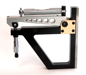
Here is an idea - just to ponder:
using this set-up - and in the absence of gauge block ownership - could you fit a micrometer screw/spindle into the angle base for the sine bar, in the position where it will touch the deflected roller?
That would allow you to quickly and easily adjust the angle against an existing taper or a precision protractor.
I'm considering this thought because I happen to have a spare micrometer spindle and no gauge blocks..... I believe a sine bad could be home-made for this purpose - or am I way off?
Thoughts?
Joe
edit: hang on a sec, looks like other people have figured this out too:Last edited by jhovel; 12th Jun 2012 at 11:21 PM. Reason: found an image of what I was thinking....
-
12th Jun 2012, 11:43 PM #15
Diamond Member
- Join Date
- Mar 2011
- Location
- Dural NSW
- Age
- 82
- Posts
- 1,203
Joe Originally Posted by jhovel
What an excellent idea, to use a micrometer for the Sine Bar instead of gauge blocks.
I have just recently purchased a set of low price gauge blocks from the USA.
Before that Ive been using feeler gauges bunched together & or Starrett adjustable parallels.
The micometer would work well
regards
Bruce
ps
Ideas never stop on this forum.

 Reply With Quote
Similar Threads
-
turning tapers.
By wm460 in forum METALWORK GENERALReplies: 26Last Post: 15th Feb 2011, 11:09 PM
