

 Thanks:
  Likes:
  Needs Pictures:
  Picture(s) thanks:
Results 61 to 75 of 188
Thread: HM52 CNC Conversion
-
6th May 2010, 03:52 PM #61
 Most Valued Member


- Join Date
- Jun 2008
- Location
- Victoria, Australia
- Age
- 74
- Posts
- 5,080

Hi Eskimo,
Just a quick and dirty check. Looking for any major defect type issues.
I mounted a lever type dial test indicator on the spindle, set up touching the table and ran the table back and forward. It's not really a test for table flatness as such. A proper test for flatness would be a lot more involved and you would need to reference against a known flat surface.
Dave recommended measuring the table thickness at the various points, this is a really good (and easy) way of doing a quick check to see if there are any major manufacturing problems. Specs call for less than 0.04 mm in 200.
Regards
Ray
-
7th May 2010, 01:50 AM #62Dave J Guest
 Originally Posted by RayG

Hi Ray
Good to hear your happy with the mill they supplied. Like you I picked it for it's Horizontal/vertical versatility, which has come in handy a few times. When it is CNCed you will have a H/V CNC mill and a lathe all in one.
I am happy with my mill now that I have gone through it, in tramming I get 0.0 all round. The table is and hardened top and bottom and nicely ground. The old mills never came with hardened tables, have you checked to see if yours is? To check it, run a file on the front or rear edge lightly and see if it cuts or just slides across it, the ends aren't hardened so don't try there. I can see slightly different color small circles on the table in the right light from the hardening process as well.
As for serial numbers my first mill was 10452B, the 52B I have now is 0902042.
Maybe all the talk about the quality and accuracy of these mills and buying a container load from elsewhere, has shaken up there supplier to produce a better quality product.
Dave
PS
I talked to a bloke today that told me he looked at the second hand HM52 mill they have in Sydney. He said it's a 2007 model, might be one of the one's I sent back.
-
7th May 2010, 09:01 PM #63
Most Valued Member
- Join Date
- Jun 2008
- Location
- Victoria, Australia
- Age
- 74
- Posts
- 5,080
Hi Dave,
The table appears to be hardened and ground, a file just skates off, also, the ends aren't hardened, as you pointed out, and the file bites a little.
First job will be to work out how to machine and fit the x-axis ballscrews. That should be a good starting point for the conversion. The Y-axis after that, and leave the z-axis (quill) to last.
My son has taken over the mill, and I can't get near it at present , he is busy making the parts for the support arm for the CNC control panel.
Regards
Ray
-
7th May 2010, 11:52 PM #64
Most Valued Member
- Join Date
- Jun 2008
- Location
- Victoria, Australia
- Age
- 74
- Posts
- 5,080
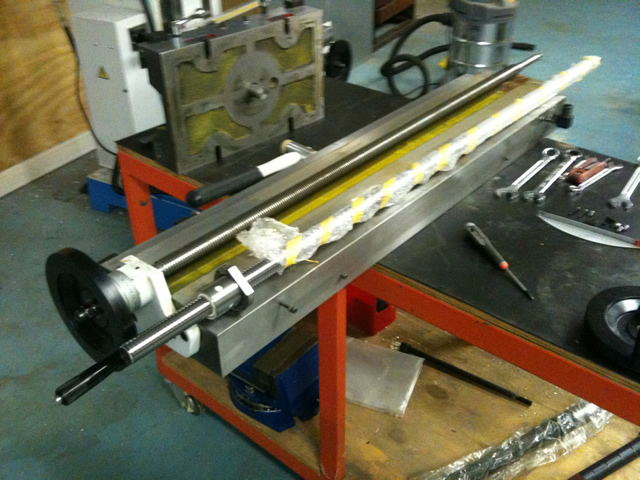
First stage of the X axis ballscrew conversion, is to pull it all apart and make a few measurements.
The table is heavy, so a trolley was set up and the knee height adjusted to take the load.
The DRO and coolant drain disconnected, and the x-axis power feed, handwheel etc removed.
Seems to me the critical measurement is the location of the center line of the ballscrew, the ballnut is slightly larger and that will move the center line down a few mm's. The old leadscrew nut appears to be cast bronze.
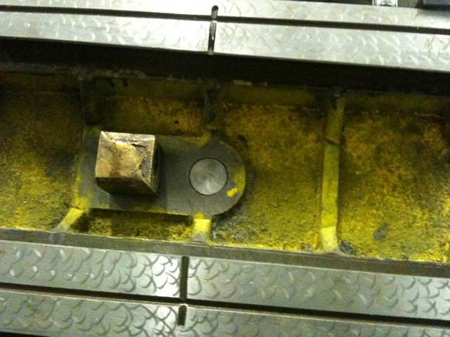
No retaining bolts, just a pin.

The bottom of the leadscrew nut is the recessed bronze pin on the right.
The casting for the table has a bit broken, they probably thought no-one ever looks under here...
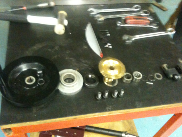
The bits and pieces of the power feed end of the table.
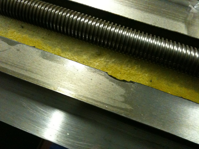
The new ballscrew being accurately checked for length...
The top of the Y-axis, what is that screw for?

The plan is to design the parts required, get the measurements right. re-assemble the machine, make the parts, dissassemble again... install ballscrew and repeat until I get it right?
One design decision has been made, and that is to fit the servo at the left hand end, that's where the existing (cheap and nasty) thrust bearing is located, and the free end is on the right hand side where the power feed is currently located.
Regards
Ray
-
8th May 2010, 12:32 AM #65Dave J Guest
Hi Ray,
I see theres no mucking around with the CNC conversion.
The edge missing on the table wont hurt as that part doesn't come into contact with anything anyway.
The oil slot/passage needs to be fixed because when you pump the oil in it will go the easiest route out the side. I had a couple that come really close and used quick steel (after spot sand blasting) to plug the ends to stop the oil coming out. As it's setting (5-10 min) you shave it level with a stanley knife blade.
I will be watching with interest on how you install the ball nut. Chich mounted it on one end, but reduces a bit of travel.
Dave
-
8th May 2010, 12:47 AM #66
Most Valued Member
- Join Date
- Jun 2008
- Location
- Victoria, Australia
- Age
- 74
- Posts
- 5,080
Hi Dave,
Still thinking about the best way to mount the ballnut, this is how we are currently thinking
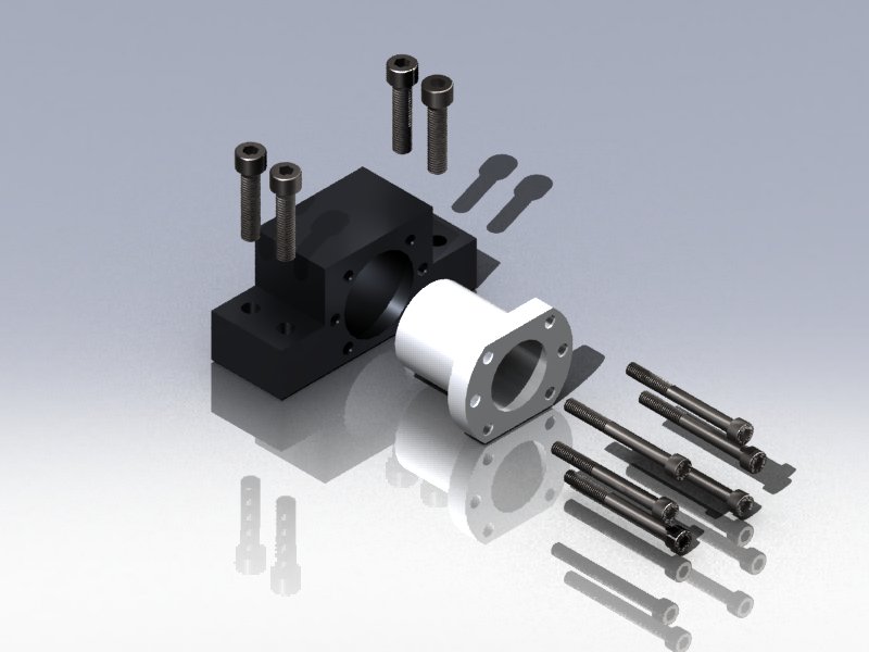
Josh is the solidworks wizard, that did the drawing...
The discussion point at present is how we machine the mounting point for the ballnut mount. I need another mill..
The existing leadscrew center line is 19mm above the current mounting surface, the ballscrew will be 24mm if we use the same surface, so the centers of the bearing support will be 5mm lower than currently.
Which oil paths were you referring to, and what would you recommend to change? ( EDIT ah, don't worry I get it!!, plug them)
:
Regards
Ray
-
8th May 2010, 01:17 AM #67Dave J Guest
Hi Ray,
You can swivel the top of the saddle 180 clamp it down then mill it using the Y axis. If you are using a small cutter and need to make a few side by side passes swivel the head across by unlocking the column bolts.
The picture looks good and I like the design. With the oil paths I cant see the end one's but those middle ones are cut through the sides were they should stop short.
Dave
-
8th May 2010, 01:51 AM #68
Most Valued Member
- Join Date
- Jun 2008
- Location
- Victoria, Australia
- Age
- 74
- Posts
- 5,080
Hi Dave, Originally Posted by Dave J
Yes, that's pretty much what I was thinking, the tricky bit about machining the ballnut mounting on the crossslide is I don't want to have to move the knee or quill once we start, so at some point we will have to make small a cut by rotating the head while the mill is running, (I'm a bit nervous about that) once on a new cut the Y axis should do the job.
I've got a bit of time to think about it, the mill has to be re-assembled and parts made, then dissassembled and then after that the machining of the mounts can be done.
The main task at present is to get the design of the servo mounting plates and AC bearing mounting. Which reminds me, I have read a few posts on CNC zone where they have just stacked the bearings without shims and the preload is pretty good. I guess shims can be added later if needed. I will post a drawing of the bearing set up, Josh has most of it drawn up already.
Regards
Ray
-
8th May 2010, 02:11 AM #69
Golden Member
- Join Date
- May 2003
- Location
- Perth WA
- Posts
- 526
I would be putting slots in the main ballnut housing to get a bit of sideways adjustment. A little out on alignment and the ballscrew binds - you will hear a grinding noise. You can adjust the mounting up with shim with that mount or skim a bit off to get it down. A slight twist in the nut itself will cause binding along the whole length of travel.
Alternatively you can slot the ballscrew mounts on the ends of the table to do the same thing. May be the better way to do it because you have room to dowel it in place once you get it right.
The ballscrew is most likely to bind near the ends as there is a little flex in the screw towards the middle travel.
The nut on the standard screw floats a little for this reason but with a ballscrew you need to get this area aligned spot on.
Hope that makes sense and I haven''t made it sound too difficult. As long as you have a little adjustment there and some patience it is quite doable.Cheers,
Rod
-
8th May 2010, 02:12 AM #70Dave J Guest
Hi Ray,
I would just use the knee DRO to reposition it in depth for each cut and it should be fine. If your worried, after cutting most of it out you could run a fly cutter over it to cover the whole lot in one pass.
Dave
-
8th May 2010, 03:36 PM #71
Most Valued Member
- Join Date
- Jun 2008
- Location
- Victoria, Australia
- Age
- 74
- Posts
- 5,080
Hi Dave, Rod,
Good point Rod, that could be a problem... been thinking about the different ways we can align the ballnut rotation to solve that problem. Another problem is once we get it aligned, the capscrews bolting it to the crossslide are covered by the table, and can't be accessed to be locked down. So I'm thinking that the capscrews should come in from the bottom with either slots or slightly oversize holes and cut the thread in the mounting block. That way I could do the retaining screws finger tight, run the ballscrew end to end a few times to pull it into line and then tighten it up, run end to end a few more times, then install the table and crossslide as a single unit. That covers the alignment of rotational aspect of the ballnut.
I'm thinking the free end (right hand side) will use the existing dowelled plate and bearing, to make that work we will have to machine the ballnut crossslide mounting down 5mm from the current surface, that means the axis of the ballscrew will be the the same as the axis of the existing leadscrew.
At the servo end, we have the new servo mounting plate and AC bearing block, the plate mounting can be slotted so that it can be aligned to be on the same center as the free end. Then dowelled at that position. (Arrggh help...how do I transfer the existing dowell centers to the new plate?) (make some dowell points?)
Josh has drawn up the assembly, and notes that we need to reference all our vertical measurements (for the machining) from the ground face of the crossslide.
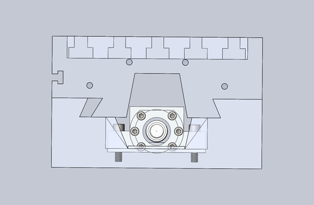
This is the crosssection view, at the ballnut location, the drawing needs to be re-done with the screws coming in from the other side, for reasons discussed above. but notice the clearance between the bottom of the table dovetail and the top corners of the ballnut. Looks like these will have to be chamfered to make sure we have plenty of clearance.
Regards
RayLast edited by RayG; 8th May 2010 at 04:07 PM. Reason: clarified chamfer
-
8th May 2010, 04:19 PM #72
Golden Member
- Join Date
- May 2003
- Location
- Perth WA
- Posts
- 526
Hi Ray,
Yes coming from the underside to the ballnut mount makes sense.
As for the dowels that is an issue particularly if they are tapered dowels. Perhaps do the best you can with the dowel points then ream oversize to pick up any discrepency. There are more than likely more knowledgable people on here that can help with that.
You are moving along quite rapidly and acolades to Josh for his solidworks drawings. A great project for the both of you.
Cheers,
Rod
-
8th May 2010, 04:43 PM #73Dave J Guest
Hi Ray,
I am not using the dowels on the end of my table. The bearing retainer and the power feed bracket were both twisted and out of alignment from factory on mine.
If you want to use dowels I would drill new ones when you have everything in it's final position.
Coming up from underneath sounds a good idea for the bolts to hold the ball nut.
Dave
-
8th May 2010, 05:53 PM #74
Most Valued Member
- Join Date
- Jun 2008
- Location
- Victoria, Australia
- Age
- 74
- Posts
- 5,080
Hi Dave,
Yes good point, the dowells are really only insurance against accidental movement and ease of re-assembly. I guess it depends on exactly how much more critical the alignment will be with the ballscrews versus the leadscrew.
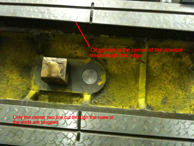
Meantime, I am looking at the oil grooves at the bottom of the crossslide, I think that they are actually meant to be cut through the side, as there is an oil groove running along the corner of the dovetails. I'm thinking that this is to get oil into the dovetails.
The oil grooves at the ends are stopped.
Here is the picture I'm looking at..
So, this model is a a bit different to yours, here is your picture (hope you don;t mind me reposting it) and I can see why you had to modify yours, the oil would have just run straight out the sides.
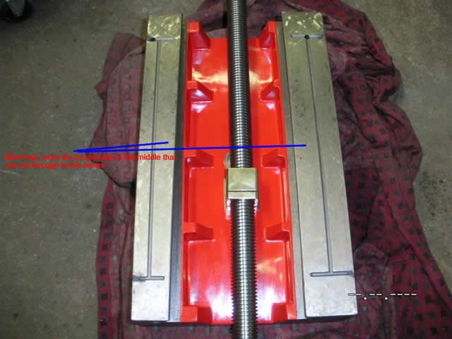
Man, I like the finish you managed to get on that casting... I should do the same, only problem is that I'll have to find another colour... maybe blue? How did you smooth out the casting like that?
Regards
Ray
Edit: Here are some better pictures
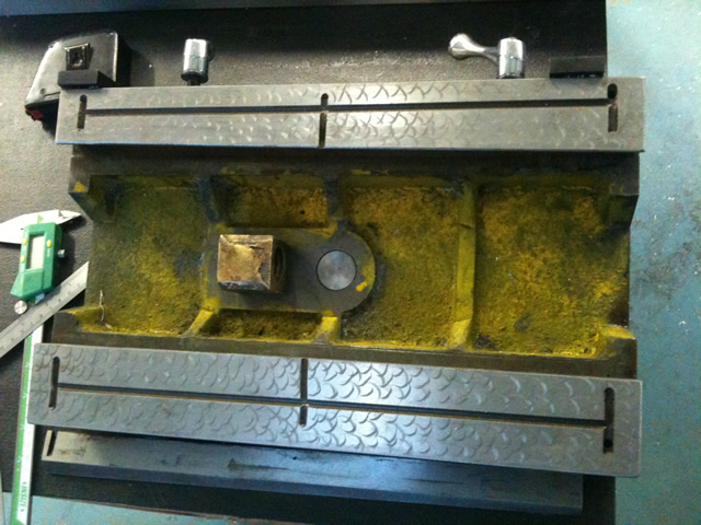
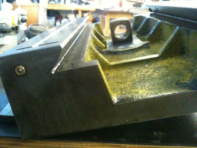
That groove in the corner, is what I'm thinking is an oil groove?
-
8th May 2010, 07:29 PM #75Dave J Guest
Hi Ray,
I have never seen it done that way but I think you may be right, so leave it as it is.
Is there a groove cut in the top side of gib as well, to get the oil over to the sliding surface between the gib and the table.
I had a look a chich's and he seems to have a groove in the middle of the non gib side only.
http://www.cnczone.com/forums/attach...1&d=1161409420
Most mills have that groove in the corner on all dovetails, I am pretty sure it's just a relief for the dovetail cutter/grinder. I think in this case if anything to do with oil, it would be an oil drain being on the bottom.
I spent a bit of time cleaning up the casting with rotary burrs 4inch grinder etc. After it was degreased and clean, I gave it a coat of car body filler. I didn't cut any meat out of it like the ribs going across, I just filled it to that level tapered to nothing at the ends, for ease of cleaning and to give me a clean base to start my CNC conversion.
A trick with the body filler is to not mix it to strong and have a jar of thinners ready. After applying the filler, use a paint scraper dipped in the thinners to smooth it. This method saves hours of sanding in confined spacers. I wouldn't use this method on a car, but I find it's fine for machinery etc.
Dave


 Reply With Quote
Similar Threads
-
Hafco Hm52 on the fritz again
By Retromilling in forum METALWORK GENERALReplies: 25Last Post: 12th Aug 2009, 11:14 AM -
CNC conversion
By sonic_racing in forum METALWORK GENERALReplies: 7Last Post: 18th Jan 2009, 03:11 PM
