

 Thanks:
  Likes:
  Needs Pictures: 0
 Picture(s) thanks:
Results 1 to 15 of 90
Thread: DIY TIG Pedal
-
6th May 2020, 08:28 AM #1
 Golden Member


- Join Date
- Sep 2009
- Location
- Sydney
- Posts
- 666
 DIY TIG Pedal
I love my DC TIG welder and I also really love welding too. Ive move on from a stretch start DC TIG to a HF Start, pulse DC TIG with remote control.
The remote part hasnt been fully used yet and Im really trying to get a foot pedal up and running but apparently this type of welder doesnt really fully utilise a foot pedal. So thats my challenge. Make and design a foot pedal to work with my welder and upgrade the cheap eBay one I bought.
I bought the eBay one to ultimately use on the machine but its too flimsy and I dont like how stiff it is. Its been very useful to understand the principles though and Ill take a few parts out of it potentially.
The frame has to go as I dont like its too thin and it moves around because its too light. Ill be using TOTs design as my foundation as it offers plenty of opportunities to make stuff:
https://youtu.be/-P6w-tj8_Tk
Unfortunately I dont have large c channel sections of steel so Im going to try and make mine out of square and rectangular tube and clad it in Alu sheet (riveted). It will be heavy but I think this will make it not move too much under foot. The blue frame here will have another on top with risers to attach the two. Will take the weight of a truck.
D61275AA-2433-4D2A-8AAC-C0DE50F2CC52.jpg
You can see the eBay peddle behind it. Bent sheet metal.
Im going to try and make the foot pedal part out of some 50x25mm tube and split it down the middle or channel out the back of it to sit over the top of the lower box.
C4B7513A-E06E-4167-A709-05BA9A8460D9.jpg
On the electronics Ive worked out that my welder needs a 1k variable resistor to adjust the amperage. Simple! Just swap out the 10k one I have in there now for a 1k, I have one on order already too.
However it gets complicated when I want to have an adjustable pedal. My welder appears to use a simple rheostat setup and the current eBay pedal uses 2 pots to adjust the voltage. One on the pedal and another in series. What this does is adjust the pedal down, however would render the first part of the travel useless (as the resistance would still be above 1k) which would make timing starting the arc very difficult as the HF would kick in but minimal (to no) amperage.
My googling last night found the option to run a second potentiometer across the first (parallel) as a way to adjust the total value of a pot. This has a side effect of impacting the sweep characteristics but I hope it would allow me to adjust the pedal down to keep the maximum travel of the foot control, but limit the maximum amperage full throttle would unlock in the welder. It would also hopefully mean the start of the foot travel will always coordinate the switch with low amps. The formula for the parallel setup is: (R1 x R2)/(R1 + R2)
I think this means I need a main 1k pot and use the 10k pot from the old pedal.
Will be bench testing the setup to see if I can get it to work before I do too much welding.
-
6th May 2020, 06:24 PM #2
Golden Member
- Join Date
- Sep 2009
- Location
- Sydney
- Posts
- 666
DIY TIG Pedal
I managed to test the concept a little by taking apart my 10k torch and adding in a 1k resistor across the pot max and wiper. It now adjusts the machine across then full range of the potentiometer but the sweep is a little fast low. Maybe a consequence of how Ive done the conversion as I wouldnt expect that sort of taper.
Leads me to believe I have some options for how I want to manage the pedal.
I also tested some ideas of adding in a potentiometer in series (which is what the pedal did originally. My understanding of the reading Ive been doing is that this will lift up the resistance values. So if I have a 1k pot and add in another 1k pot in series this would add the value on the beginning and end. Not ideal in my case Im thinking as if my machine needs 1k and it now starts at 1-2k, maybe the pedal wont work until half way... not good if Im after fine control.
So with that in mind I have a couple of concepts to try.
1. Add a simple pot in series and hope the initial part of the pedal still provides enough taper to work at low parts.
2. Execute a complicated mix of pots and resistors to achieve an adjusted potentiometer range and max value.
Option 2 I have taken through to data stage. I created a spreadsheet and added in the following items:
1. Main pedal potentiometer 1k
2. Range adjuster potentiometer across the max and wiper of the pedal pot. Will also have a 1k resistor in series to stop it going down to zero (making it a 1k - 11k pot)
3. Limit adjusting potentiometer in series with the pedal wiper
The idea here is that you have the option to adjust both pot 2 and 3 to deliver different options. As an example:
Pot 2 max, pot 3 min (Standard pedal)

Resistance is almost in line with the pedal pot on its own.
Pot 3 used to lift the pedal max to a certain value (eg rather than full open, limit to 40%), pot 2 adjusts back the starting resistance:

Here I can set the pedal to max out at 40% and the pot 2 is used to adjust back the starting point to 1k.
Im worried about the taper so found a great resource on line to check the impacts. It appears to make almost no difference to the taper which is promising:

https://sites.google.com/site/garyda...ectronics/java
The plan is to setup all of this on the bench and play around with it and see if the results are close to useable. The parts are ordered already though Mouser. Im happy enough to progress the frame build, so will update as that moves along too.
-
6th May 2020, 07:45 PM #3
Steel Panther
- Join Date
- Dec 2018
- Location
- NSW
- Posts
- 586
Short of making the pedal from scratch like you (I have a spare foot pedal shell to work with), I have gone through a similar thing.
I converted a R11F pedal to work in place of a 3-pot pedal that works with my boc 185 tig. The r11f is a kemppi pedal and is a dream to use but needed modding to work.
Another project I want to try is modding a stick welder that has liftarc tig capability to work on a pedal. this would effectively allow a $300 machine to work like a more expensive one, less the HF start.
For this, the pedal would just need a 1K ohm pot instead of the 10K that is fitted in my case, and then to toggle between pedal and amp dial on the machine itself, just tap in a SPDT switch to switch between the control methods. Easy to mod into most machines if you don't mind drillin' holes!
Keep us updated. I like this kind of stuff.
-
6th May 2020, 10:04 PM #4
Most Valued Member
- Join Date
- Mar 2011
- Location
- Southern Flinders Ranges
- Posts
- 1,554
If your pot has really quick value change at one end it may be a logarithmic sweep. Pots come in log or linear, you need a linear one for this application.
Following along with interest, I’ve been considering buying a miller wireless one to see if I can make it work on my machine.
-
6th May 2020, 10:07 PM #5
Golden Member
- Join Date
- Sep 2009
- Location
- Sydney
- Posts
- 666
DIY TIG Pedal
I checked that tadpole. 1/4 turn is 25%, 1/2 turn is 50%, 3/4 turn is 75%.
Its an odd one why the ramp up is so quick but all my testing so far is with 10k pots. I hope the 1k pot adjusts this but will have to wait and see.
However if it doesnt, I could actually look at an audio taper to correct the problem potentially.
-
7th May 2020, 07:59 AM #6
Steel Panther
- Join Date
- Dec 2018
- Location
- NSW
- Posts
- 586
If for nothing other than comedic relief to this thread, this is the (poorly drawn) diagrams I drew up for the OE model I was using, and the franken-pedal I made.
This particular machine uses a 3 potentiometer system
10K pot for the foot pedal actuation- ie the user input pot.
There is a max and min pot, a 1K and a 10K respectively. Max pot trims down the max amp setting, min pot modifies the starting amps.
So with this machine (YMMV), I can dial in an amperage 'window' and have control within that space. Useful so you don't blow the out of a 1.6mm tungsten and your job if you fumble the pedal.
Machine gets set to max on the face plate, or somewhere in between, to set the max available current, and 'max' on the pedal modifies up to, and less than that output.
For my machine, max sensing voltage I saw was 9.5V
IMG_1751.jpg
IMG_1806.jpg
-
7th May 2020, 11:12 AM #7
Golden Member
- Join Date
- Sep 2009
- Location
- Sydney
- Posts
- 666
DIY TIG Pedal
Sounds like youve done exactly the same as me, except my wiring is rheostat based not voltage decider that makes things a little simpler for me.

Same process too. My welder doesnt offer machine max amp adjustment in remote mode so it all has to happen in the pedal.
Im going to add in a switch to the pedal too that will deactivate the foot switch when the pedal is pressed, so adjustments can be made without the HF start going off.
Step 1: set min/max pot to get maximum amps
Step 2: set slow/fast pot to adjust starting point of foot control
I popped in to Jaycar this morning too and bought some cheap components to test the concept. Im amazed to find it works!

I also bought an audio taper pot to see if I can get more low amp control. Will hook it up with crocodile clips to test the concept on the welder before loading in to the foot control chassis.
-
7th May 2020, 02:46 PM #8
Golden Member
- Join Date
- Sep 2009
- Location
- Sydney
- Posts
- 666
Had the readings working on the bench but for some reason the 2 additional pots are doing literally nothing.
I will have to setup a different type of rig and see how I can get that working instead.
I know its adjusting a 7v feed on the potentiometer, just not sure why my thoughts to adjust the sweep arent working.
Back to the drawing board.
-
7th May 2020, 05:03 PM #9
Golden Member
- Join Date
- Sep 2009
- Location
- Sydney
- Posts
- 666
DIY TIG Pedal
New setup. Have the old pedal apart for the amp control and have it wired up on the bench instead. Thought it could do any damage with 7v on a towel plus allows me to test different setups.
Managed to get it working with just the main pot and a 10K pot over the input and wiper on the pedal pot.

With a standard pot it looks to have a really smooth sweep across the amp range. Theres a wait till the pedal starts climbing from 20a but thats more than manageable I think. Plus the additional 10k pot allows for max amp adjustment and I cannot really see any impact on the starting current.
-
7th May 2020, 10:21 PM #10
Golden Member
- Join Date
- Sep 2009
- Location
- Sydney
- Posts
- 666
DIY TIG Pedal
It looks to work. Ive gutted the old pedal and loaded in new pots. I also cut some steel tube this afternoon ready to give the pedal a try but unfortunately my grinder cut tubes are ordinary when it comes to fit up (as they always are).
I wanted to avoid it but I had no choice but to improve the fit. I do this with most of my tube to get the correct angle for welding, put it in the mill and hog off the ends to a true 45 degree with a 12mm roughing end mill:

It makes for a beautiful fit:

Unfortunately its pretty late here, whilst the mill is relatively quiet, the grinder with a flap disc would not be. So tomorrows job will be to clean up the ends and bevel the edges ready to weld.
These 2 frames will sit on top of each other with some small risers on each corner. Its as long as my foot and much wider. I thought the wide footprint would make it feel sturdier and also (with rubber feet on the bottom), would hopefully not slide around on the floor too much.
I wanted no open tubes because I will be making fill panels for each side out of aluminium sheet (1.5mm) and so the frame will be slightly visible all the way around.
-
8th May 2020, 07:59 AM #11
Steel Panther
- Join Date
- Dec 2018
- Location
- NSW
- Posts
- 586
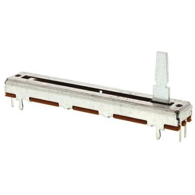
Consider a pot that works linearly, not a rotary one.
Something like this will make the mechanics of the foot movement to resistance so much easy to manage from a mechanical aspect- no messing about with springs, wires etc. They come in a range of resistances.
Other "nice to haves" would be things like:
1- Adjustable spring tension for the pedal resistance (good if you want to use your pedal out of position- while laying on the ground actuating with the side of your foot, or in between the knees... 'it' happens)
2- Adjustable stops for fully open and fully closed positions. This will help with tuning the microswitch for the arc start feature - can have it very sensitive, or after a small movement of the pedal to prevent false starts.
3- Put a cable gland thru the plate, and use some quality multi core cable. Won't snag on sharp things in use, and gland will offer cable relief for protection of the goodies inside. Maybe something more sturdy than normal trailer wire if you can get it.
-
8th May 2020, 08:58 AM #12
Golden Member
- Join Date
- Sep 2009
- Location
- Sydney
- Posts
- 666
DIY TIG Pedal
I had an idea to use a few springs to get the control tension set right but would involve removing the covers to access and adjust. How could spring tension be adjusted from the outside? The current spring on the eBay pedal is way ok strong and not a nice feel. So I want something silky smooth and not too hard to push the pedal down ideally.
I like the idea of stops too. Means I could limit current by limiting travel too as well as limiting current but still have full travel. Again have you seen any ideas on how to execute? I could set up a simple threaded rod I suppose at each end (long bolt and lock but)?
Im ok on the cable gland. Ill be taking the cable connectors off the old pedal so it all comes apart. I may look to replace the trailer cable though. Its a little stiff for my liking and with only 7v to actuate, it doesnt need to be as thick as it is I dont think.
-
8th May 2020, 05:55 PM #13
Most Valued Member
- Join Date
- Sep 2012
- Location
- York, North Yorkshire UK
- Posts
- 6,477
Hi Neevo, Originally Posted by neevo

Use a cam ! A simple disc with a pin in it to locate the spring. A screwdriver slot on the shaft and lock nut to secure the setting.Best Regards:
Baron J.
-
8th May 2020, 08:11 PM #14
Steel Panther
- Join Date
- Dec 2018
- Location
- NSW
- Posts
- 586
The way the kemppi pedal works, is the spring is compresses as the pedal is depressed.
The spring has a bolt through the middle and a wear pad, and a simple spring perch that rides along the bolt thread will preload the spring. I guess it's a rising rate spring...
Set your spring on the furthest feasible point from the pedal fulcrum.
As for pedal stops, maybe just weld a nut in there and a thru bolt and lock nut to set it at that height?
Bit hard to give specific advice without knowing too much of the form factor that you are working within.
-
8th May 2020, 09:46 PM #15
Golden Member
- Join Date
- Sep 2009
- Location
- Sydney
- Posts
- 666
Step one is semi complete. I also got to try out a pedal for the first time. A few observations of welding with a pedal:
1. This eBay one works but isnt very nice to use. The spring is too stiff and the throw to get to 100a is too much. Im with you commander, a stop would be great so I can tailor the travel to get max amps. Full throttle of the pedal is too much throw I think, although its nice to have the option.
2. Welding control is another level. Can hit the weld hard at the beginning then taper off as you get through the weld. Control is incredible and I was able to easily weld the corners of the 45 degree cuts without blowing through once.
3. Its going to take some getting used to and its probably highlighting some bad technique but I can see the benefits. I found I was able to get some nice beads but most were a little hot. Not a major issue as I dont want to have to grind them back too much and this way its a lot less work.
So I give you the brick house pedal box:


Ill be actuating the pot in the middle via a string and pulley as per the TOT video. Havent figured out the pedal spring mechanism yet but not a fan of the one on the eBay pedal (a coiled spring around the pivot).
Doing it all on the fly with only a rough idea what the plan is.

 Reply With Quote

Similar Threads
-
Tig pedal for a poor man
By jackaroo in forum WELDINGReplies: 38Last Post: 4th May 2020, 08:52 PM -
Cincinnati pedal power
By tongleh in forum METALWORK GENERALReplies: 13Last Post: 9th Nov 2012, 06:54 AM -
Left Foot Accel Pedal Update
By Sterob in forum METALWORK GENERALReplies: 3Last Post: 9th Aug 2011, 03:39 PM -
Foot pedal question
By oo7fitzy in forum WELDINGReplies: 5Last Post: 25th Apr 2010, 10:46 PM
