

 Thanks:
  Likes:
  Needs Pictures:
  Picture(s) thanks:
Results 1 to 15 of 32
-
4th Mar 2016, 12:52 PM #1
 Senior Member


- Join Date
- Dec 2014
- Location
- Tasmania
- Posts
- 102
 Hercus radius turning tool - project
Hi all,
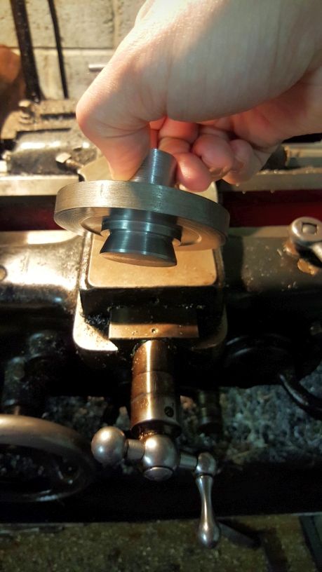
I have started making a radius (ball) turning tool for my Hercus 9A and phase one is complete, the base with the round dovetail is done and fits snugly in place in the cross slide.
I'm not working to a plan as such here, just kind of reproducing what I have found searching other forums and google etc. The next step is to decide how I want the top rotary table part to attach to the base. I am thinking that I would like it to be attached on a bearing, perhaps just a plain cartridge bearing with a press fit. Any ideas or suggestions are welcome, I'm not taking it too seriously just been spending 30 minutes here and there when I can, that base took me 2 weeks!
The other consideration obviously will be about how the toolpost and slide arrangement will work. I have seen some with grub screws and others with threaded rod running through the toolpost with a knob for adjustment.
I will try and post more pics as I go along here.
Cheers,
ratters
-
4th Mar 2016, 01:28 PM #2
Most Valued Member
- Join Date
- May 2011
- Location
- Murray Bridge S Aust.
- Age
- 71
- Posts
- 5,959
Looking forward to seeing this project develop.
KrynTo grow old is mandatory, growing up is optional.
-
4th Mar 2016, 11:50 PM #3
australian metalworking hobbyist
- Join Date
- Jan 2009
- Location
- Holbrook, NSW
- Age
- 73
- Posts
- 490
You're on the right track. I made a rough one just for putting the radius on the tailstock handwheels, so it's quite limited. Your's will need to be a bit different in the toolholder to accommodate lots of different radii. I include a rough photo which may help. Mine has 0.0005 clearance between the plates, which are fully ground. It operates very freely, without any vibration and gives a beautiful finish.handwheel-radius-turning-to.jpghandwheel.jpg
-
15th Mar 2016, 08:52 PM #4
Senior Member
- Join Date
- Dec 2014
- Location
- Tasmania
- Posts
- 102
Update-
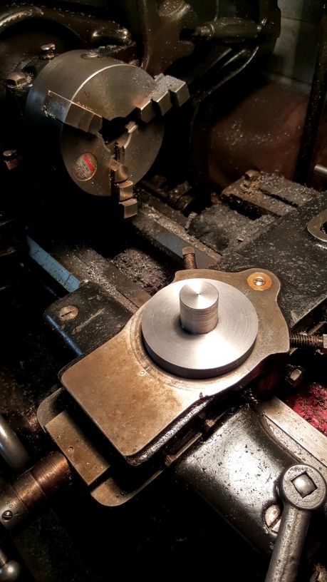
In the spirit of 'using what you have' I decided to re-use the old spindle thrust bearing which I replaced in the lathe headstock last year. Still serviceable when I took it out but was getting noisy so it's more than suitable for this task (I hope). Just finished machining the recesses for the bearing races and its all nice and snug.
Next step will be turning down the centre shaft and putting a thread on the end of it so I can hold the two pieces and tighten them together, maybe with a nylock nut. The nut will be recessed and sit underneath the tool post slide.

-
20th Apr 2016, 09:58 PM #5
Senior Member
- Join Date
- Dec 2014
- Location
- Tasmania
- Posts
- 102
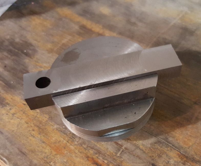
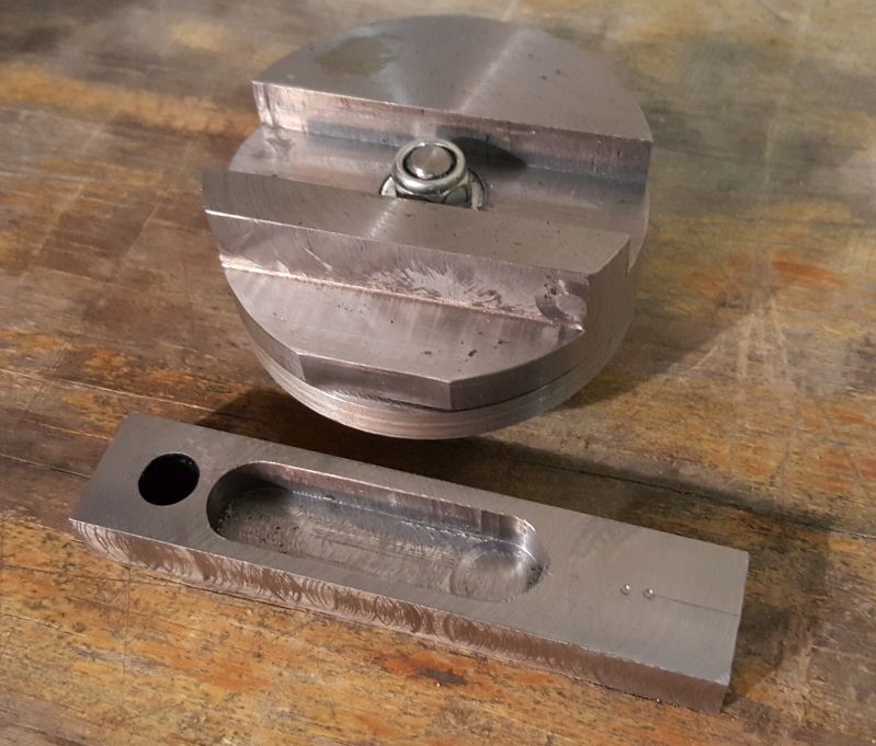
Some more progress made, I have milled out a slot and made a matching toolpost slide. Due to sort of making it up as I went along a bit, I didn't realise I wouldn't have enough material in the top plate to allow the slide to clear the fastening nut. Seems to have been solved with a recess cut into the slide however and I'm happy enough that it will be fine. Still need to drill and tap holes for the grubb screws, and I'm currently working on the toolpost which I have decided will have carbide bits.
Quite happy with it thus far, the nylock nut allows for good pressure to be applied yet still rotates freely, and thankfully it feels great with the bearings, no movement that i can feel by hand. She's a bit rough but I'm OK with that
-
21st Apr 2016, 08:10 AM #6
Philomath in training
- Join Date
- Oct 2011
- Location
- Norwood-ish, Adelaide
- Age
- 59
- Posts
- 6,561
Did you find this thread? a few more ideas and pics here - Originally Posted by ratters

//metalworkforums.com/f65/t163049-ball-tool
Michael
-
21st Apr 2016, 05:50 PM #7
Member
- Join Date
- May 2015
- Location
- Newcastle
- Posts
- 62
Wow, I'm impressed. It's very nice, I'm looking forward to seeing it complete
-
24th Apr 2016, 10:34 AM #8
.
- Join Date
- Nov 2008
- Location
- Perth WA
- Age
- 71
- Posts
- 6,459
Hello Ratters,
A while back I made a turner along similar lines to the one you are making. On a 4 1/2" swing lathe there isn't much room between the spindle centreline and the top face of the saddle. Even with a pretty low profiled vertically rotating ball turner, running out of room is an issue. The workpiece needs be longer to provide clearance. I turned myself into a corner a number of times in the process of making one simple ball - //metalworkforums.com/f65/t1952...71#post1867471
Based on my limited experience and frustration, I would suggest trying the keep the height of the rotating base to a minimum and the incorporation of some sort of screw feed might make using the turner more convenient. If I was to make another, it would be along the lines of Michael G's up and over device.
Bob.
-
26th Apr 2016, 02:12 PM #9
Senior Member
- Join Date
- Dec 2014
- Location
- Tasmania
- Posts
- 102
Thanks for the advice Bob. I think I have a little bit of leeway with the base height still so I might be able to turn it further down for more clearance. I'm starting to see the light at the end of the tunnel on this project now, next update shortly will show the toolpost and grub screws done.
-
28th Apr 2016, 09:03 AM #10
Senior Member
- Join Date
- Jul 2012
- Location
- Griffith NSW
- Posts
- 435
Funnily enough, Im pretty well running in parralell with you on this one. I finished my base and rotating bit last weekend (took a few days to get them to my liking) and now Im milling out the cross slide part. Ive gone for a pretty different approach in some respects though, Im just using plain bearing surfaces and the stud that runs up the centre of the bearings is inverted on mine - it is attached to the rotating part and extends downwards into the base (and the hole in the cross slide). My adjustment is by a dovetail rather than a square section too.
If that doesnt make an ounce of sense, then just give me a week and ill have the thing done hopefully. Im making one in a mad rush because I want some new handles for my mill and Ive got it in my head that its three ball or nothing. Keyway nonsense will be the next problem to tackle.
-
1st May 2016, 06:15 PM #11
Senior Member
- Join Date
- Jul 2012
- Location
- Griffith NSW
- Posts
- 435
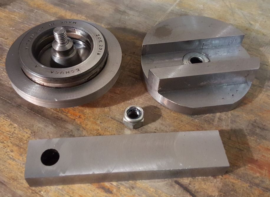
I dont want to hyjack ratters thread, but here's a few progress pics. When its completed, ill post a thread in the projects sub.
20160501_163846.jpg
As I mentioned above, I decided to make mine as a bit of an inverted version of the usual. I did it this way for a few reasons, it means I can make a larger range of balls (should I ever need bigger balls... ) and because it allowed me room to run a dovetail across the middle of the rotating plate. The dovetail doesnt really aid rigidity or anything like that, I went with a dovetail so that I had a stable platform for making fine adjustments. Although I wont bother at this point with the attachment, I plan on making a small micrometer adjustment screw for the back of the slide so that precise adjustments are straight forward to do. Ill also engrave a vernier scale on the two components to help in the meantime.
No fancy schmancy ball or roller bearings, I dont think theyre warranted really. I relieved the inside area of the planar faces so that the thrust of the cutting is taken at the perimeter. All plain bearing surfaces, just went to plenty of effort to make sure they were skookum and smooth with the final passes. A highly scientific test feel in the hands with a bit of oil seems very promising. With the oil in there, they wring together very tightly indeed.
20160501_163909.jpg
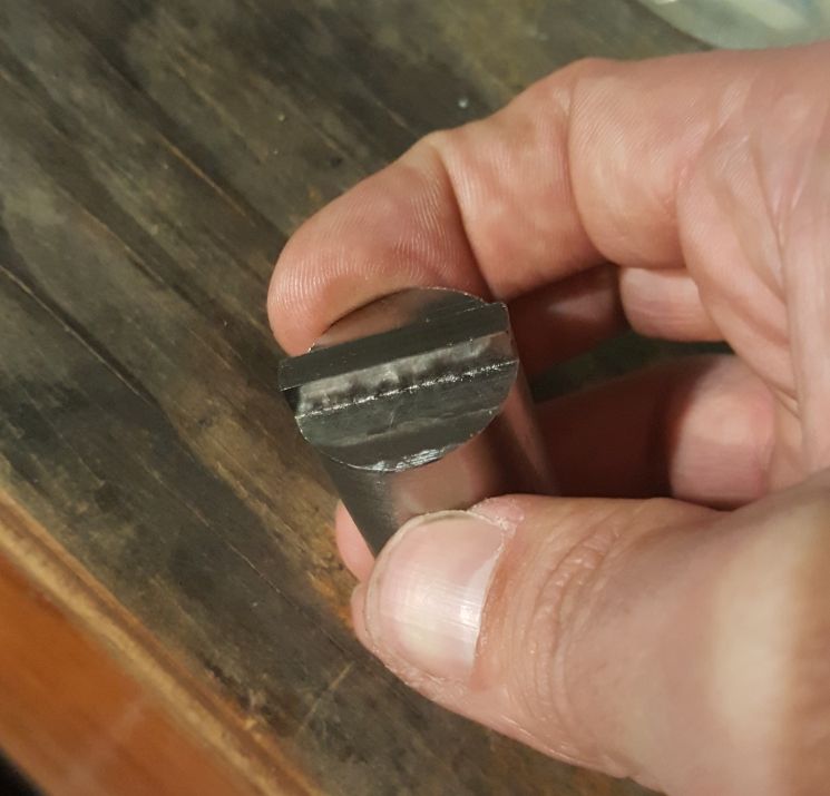
The dovetail is only 7mm deep, but it should be fine as all the forces are acting downwards. The tightening screw pulls the dovetail down, not against the angled faces. Once its loose though, it stops the sliding section from leaping away to freedom. There is a good reason for not locking the dovetail upwards or clamping the sides of the dovetail in - it would distort the rotating plate and stop it from bearing evenly on the mounting plate.
20160501_163749.jpg
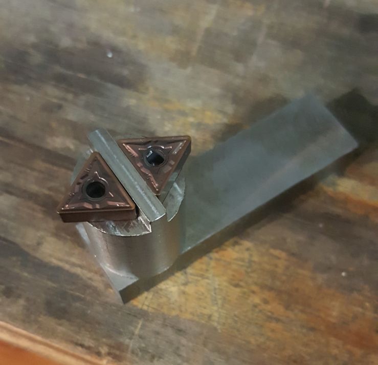
The pesky sliding dovetail section. This has been the effort of a few hours in the shed today. Ive been whittling it out from a block of 16 x 50mm steel as thats all I had on hand to do the job. In hindsight, ill stop being a tightarse and buy something closer next time. The dovetail was machined upside down and the mid section slotted out / drilled for the pillar (yet to come) and then I flipped it over to start removing all the waste from the top. I got a bit carried away with it last night and the 80mm shell mill attempted harakiri. One of the inserts is no longer interested in removing metal and the workpiece moving had partially sheared two bolts holding it in place. I got a bit more serious about bolting it down after that little mishap!
-
2nd May 2016, 11:56 AM #12
Senior Member
- Join Date
- Dec 2014
- Location
- Tasmania
- Posts
- 102
Nice work scottyd, I did originally think to do a dovetail slide myself but frankly my skills probably aren't up to it and also I have found that milling on the Hercus can be troublesome, lots of chatter at times. It's been incredibly handy to be able to do milling but honestly now I realise that what I really need is a proper mill.
-
18th May 2016, 11:53 PM #13
Senior Member
- Join Date
- Dec 2014
- Location
- Tasmania
- Posts
- 102
Some more progress made! The toolpost is not far off done, just need to drill and tap for the carbide fastening screws. I also drilled and tapped for the set screws that hold the slide, although I might shorten the screws a bit as they stick out a bit far for my liking. Also considering what kind shaping I might be able to achieve with the toolpost, its not fixed to the slide yet so I was thinking even turning a taper on it just to reduce any unnecessary material that could get in the way. Maybe just milling some flat sides on it that match the triangle carbide bits as I have seen with other peoples efforts.

-
26th May 2016, 02:44 PM #14
Senior Member
- Join Date
- Dec 2014
- Location
- Tasmania
- Posts
- 102
I have hit a snag.. The carbide inserts pictured above use a proprietary size hole and are held in place normally with a pin and clamp arrangement. The hole is 3.8mm and there is no machine screw either metric or imperial which comes close enough for my liking for a snug fit so I decided what the heck, I will make custom screws. I started with 5mm metric hex head screws and turned the shaft down so its a nice snug fit in the 3.8mm hole. But now my problem. My ******* chinese tap and die set which I was going to cut a 3x.06mm thread with on the bottom of the screw is so terrible I suspect it would struggle to cut aluminium letalone a stainless screw.. It doesn't start cutting, just chews and scrapes and generally makes a dogs breakfast of it. And this is being held in a tailstock die holder with the screw head held firm in a collet.
I suppose my next trick is to try cutting the threads with the lathe, although to date I have only done easy thread cutting, nothing anywhere near that fine so I guess I will have a crack and see what happens. Maybe if that also fails I will be forced into buying a new tap and die set. Although good sets seem to run well into the hundreds of $. Or I can rethink the toolpost situation, maybe I can get inserts with a friendly hole size?
-
26th May 2016, 03:29 PM #15
Most Valued Member
- Join Date
- Jun 2007
- Location
- sydney ( st marys )
- Age
- 64
- Posts
- 4,890
Different inserts in my opinion would be the easiest solution.


 Reply With Quote


Similar Threads
-
Not metalwork - but a machine tool for granite turning
By jhovel in forum METALWORK GENERALReplies: 6Last Post: 11th Dec 2014, 01:00 PM -
Ball Turning Tool
By Anorak Bob in forum METALWORK GENERALReplies: 86Last Post: 23rd Aug 2013, 04:22 PM -
Mini lathe/mill project No.3 Knurling tool
By neksmerj in forum METALWORK GENERALReplies: 15Last Post: 4th Jun 2012, 05:57 PM -
Turning tool shape
By morrisman in forum METALWORK GENERALReplies: 22Last Post: 14th Oct 2011, 07:49 AM -
Over The Top Ball Turning Tool
By seafurymike in forum METALWORK GENERALReplies: 5Last Post: 28th Oct 2010, 07:14 PM
