

 Thanks:
  Likes:
  Needs Pictures: 0
 Picture(s) thanks: 0
Results 1 to 15 of 89
Thread: Lathe Help
-
23rd Feb 2014, 09:46 PM #1
 Golden Member


- Join Date
- Sep 2009
- Location
- Sydney
- Posts
- 666
 Lathe Help
I've been customising a Honda CB400F (modern custom Cafe Racer) for a while now, going down the rabbit hole with the build (http://idiotsguidetocustom400f.blogspot.com.au). Its been a journey of learning and tool accumulation. One piece I've always had my eye open for has been a lathe, for various polishing and spacer making duties.
Well surfing eBay yesterday I stumbled across a 24 hr auction from a chap that looked pretty desperate to clear some gear as he had some bills due, I dropped him a text message and 5 hours later had myself a lathe for the princely sum of $320 AUD
Its a Hercus I believe (because its written on the end of it), however thats about all I know about it:
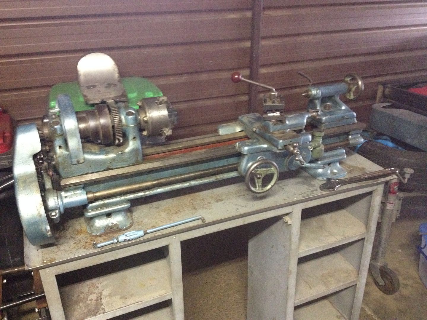
I took the time today to go through it and see what I had bought and try and work out how to get it back in to working order (not too fussed about cosmetics at this stage) and I'm hoping people here can help me fix it up. Here is the days work.
"Big day in the shed today playing around with my new lathe. I am really starting to think I got a bargain on this piece of equipment as the more I delved into it the better it worked and tighter it felt. The plan for today was to put it back together, replace missing bolts etc and generally try and run it for a second to see what I had.
First job of the day was stripping the 4 jaw chuck and getting it moving freely as it was quite tough to turn. I unthreaded it from the backing plate, undid each of the jaws, cleaned them up with compressed air and silicone spray and put them back together. Didn't really do much for the action unfortunately but at least I can say its clean in there:
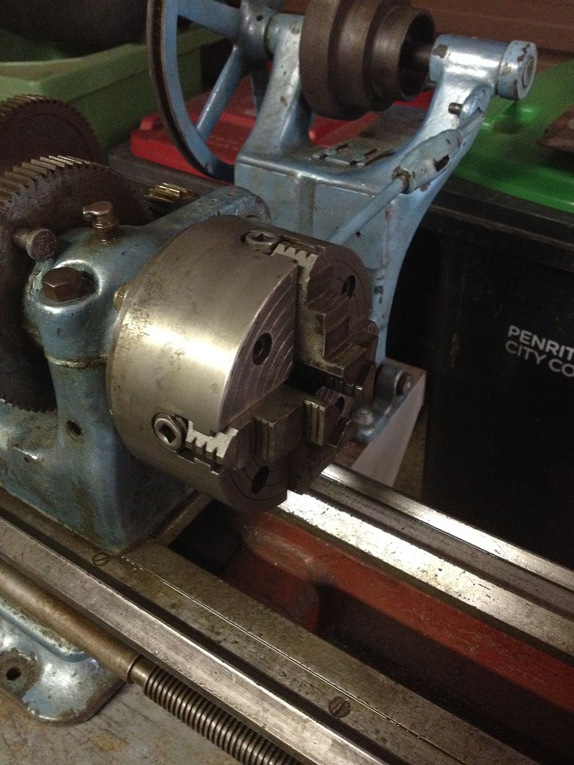
Later on I put a bolt in the jaws and I have to say it took a while to get it centred, think I will look at getting some 3 jaws as soon as possible.
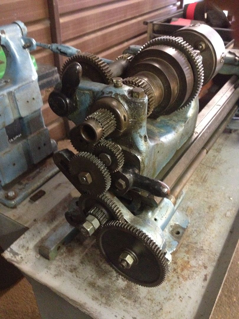
Next up I took the end cover off and inspected the end gears. I worked out the top lever is for the slow speed (also have to unlock one of the main gears on the lathe) and the bottom lever is to reverse the screw:
When I got the lathe the slow gear lever had way to much travel on it and the gears would over extend and lock up:
Turns out the adjustment on the lever was out. I found this small screw and locking nut and discovered it limited the travel of the slow gear arm, a quick adjustment and it was working perfectly:
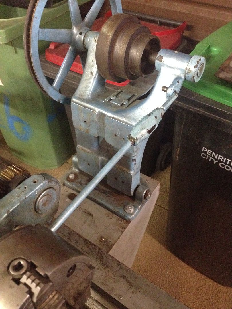
Next up I reattached the motor spindle arm and cleaned up the threads on the tensioner arm as they were full of gunk. Got it all working smoothly:
I didn't like the mismatch of bolts on the machine, so I went to my local hardware store and bough all new hardware for the lathe feet, motor spindle arm feet as well as the gear covers and motor mounts:
[img width=770 height=577]http://i258.photobucket.com/albums/hh270/edneeves/E82390E3-3936-4FDB-8857-1221596635DB_zpsqgzntzz2.jpg[/img]
[img width=770 height=577]http://i258.photobucket.com/albums/hh270/edneeves/D6C08E44-E64E-4D75-AF31-22D5802C59B5_zpsbcctu8h3.jpg[/img]
[img width=770 height=577]http://i258.photobucket.com/albums/hh270/edneeves/DA16B345-53FD-40DE-8BC4-595902B305D2_zpsfnmgbp3v.jpg[/img]
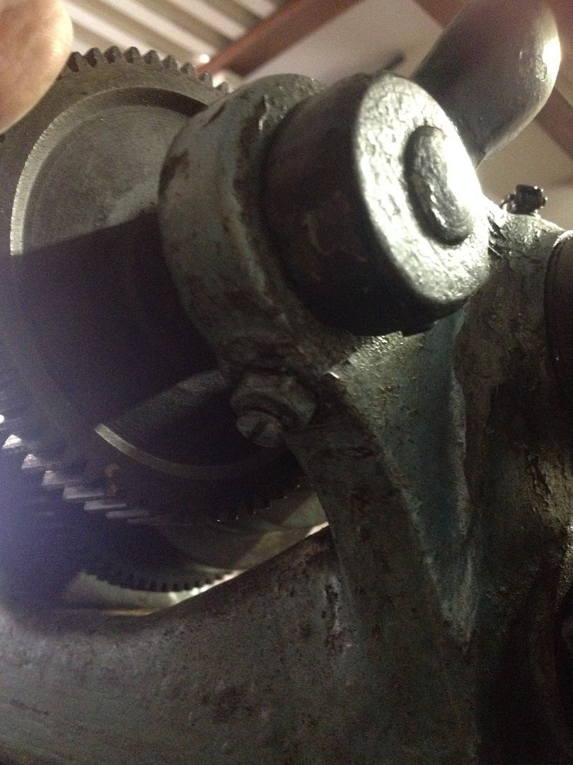
When playing with the end gears I found out that the set screw was a little loose and was jiggling around a bit:
[img width=770 height=577]http://i258.photobucket.com/albums/hh270/edneeves/265F5219-FA1C-4D14-96D1-E45019C5EB9E_zpslrqurp8q.jpg[/img]
A quick tightening of these two screws and all the slop was gone:
[img width=770 height=577]http://i258.photobucket.com/albums/hh270/edneeves/A3FC4A4D-1869-4248-851F-5EA4111F2CB8_zpsaouwtwsm.jpg[/img]
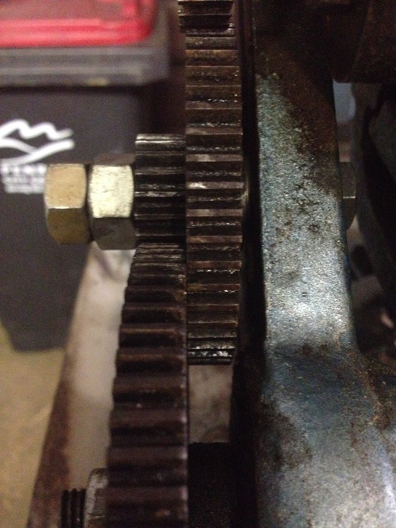
Next up was a thorough check of all the end gears as something didn't look quite right:
-
24th Feb 2014, 08:09 AM #2
Golden Member
- Join Date
- Sep 2009
- Location
- Sydney
- Posts
- 666
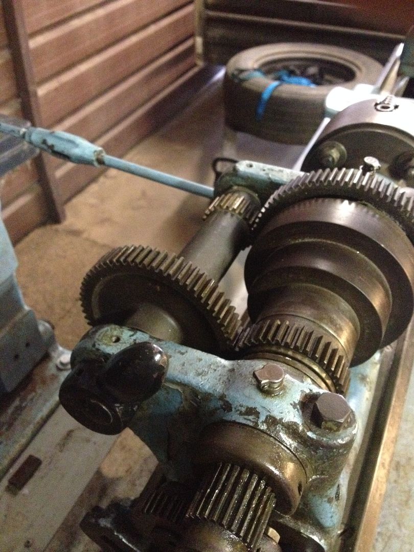
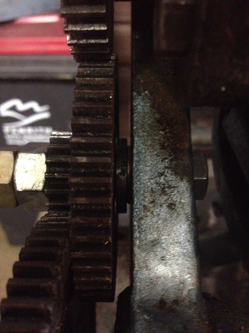
Turns out something wasn't right, the middle gear (adjustable position one) was not on the original bolt:
[img width=770 height=577]http://i258.photobucket.com/albums/hh270/edneeves/05B1D55D-9943-4184-BE19-49EA38397ED5_zpsxdbdo8cn.jpg[/img]
This hack job meant it rubbed on the frame of the lathe near the set screw cog:
[img width=770 height=577]http://i258.photobucket.com/albums/hh270/edneeves/CAC587CE-7C43-4264-999D-425F8580AC76_zpshckezyxe.jpg[/img]
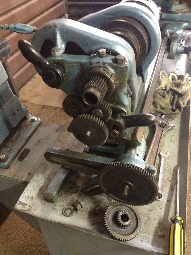
I planned to buy a new bolt for it but in the end the 1/2" I purchased didn't quite fit properly, might get it on the lathe when I'm finished and get it adjusted. I also took the time to work out which gears I have so I can try and identify which ones are missing and look to replace them:
[img width=770 height=577]http://i258.photobucket.com/albums/hh270/edneeves/8317D088-1B8E-4269-AE57-1938A5469BC0_zpsj9ibxb3a.jpg[/img]
[img width=770 height=577]http://i258.photobucket.com/albums/hh270/edneeves/B3112E73-D04E-4822-BFFD-4A641BE24A4A_zpsjbl8ccts.jpg[/img]
So I have 44/54, no idea what that means, but hopefully I can get the others to get the set screw working perfectly.
Next job on the list was to find some washers so I could space out the gears on the end and minimise the rubbing on the frame, I fixed the frame rub but got a touch of gear rub instead. Oh well, still need to work that one out:
It was at this stage I popped the motor back on and tested it, might keep it for the short term and see if I can get the lathe running before I look for a new one (variable would be ideal), I wired in a switch for the motor, screwed it to the table and ran an earth to the table too:
[img width=770 height=577]http://i258.photobucket.com/albums/hh270/edneeves/AF12E225-1FC7-46CC-9A32-6ECA91189FCC_zpsruzsjs0y.jpg[/img]
Test fire and it all worked fine:
[img width=770 height=577]http://i258.photobucket.com/albums/hh270/edneeves/9BF83C84-D397-409B-BC7C-F9ADAB8F53FB_zpsbyfqqji7.jpg[/img]
Lastly I was desperate to fire the lathe up and so took to joining the belt that came with it, it was a rough job and I decided to do it off the lathe, with the plan of taking the lathe apart a bit to put it back on. I wired up the belt fine:
[img width=770 height=577]http://i258.photobucket.com/albums/hh270/edneeves/00B63C5E-0F50-4B01-94F5-06BBFB7E1163_zps0yxhmn7p.jpg[/img]
I even worked out how to put it on the motor pulleys, however could not for the life of me work out how to disassemble the lathe pulleys to run it through there, so my plan to run the lathe failed at the last hurdle:
[img width=770 height=577]http://i258.photobucket.com/albums/hh270/edneeves/C44DFB04-FBC1-471C-B531-CC58C1036CC8_zpssgfccvso.jpg[/img]
[img width=770 height=577]http://i258.photobucket.com/albums/hh270/edneeves/5E0FC84A-550B-4520-BB09-BCBAAFD1D951_zpsx03g8nkg.jpg[/img]
So I'm pretty happy with where I've finished for today. Still need to get a belt for the main drive to the lathe and get a replacement bolt for the gears on the end, but I think I'm in a position to test the lathe and see if it will cut anything:
[img width=770 height=577]http://i258.photobucket.com/albums/hh270/edneeves/90941343-7AF5-44DA-84E8-09FCBBB81E60_zpsikbomcu6.jpg[/img]
[img width=770 height=577]http://i258.photobucket.com/albums/hh270/edneeves/373F1922-9E09-44DB-ADAD-F630953E45A4_zpsh3p7ecwk.jpg[/img]
So with all this work I have some questions and seeking advice:
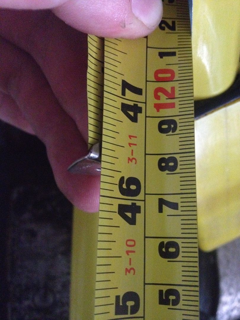
1. I am looking for a replacement belt. I have seen a fantastic video of a chap taking the spindle out of his lathe so maybe I can do that and get a continuous belt. No idea where to get one but I did measure the pulleys (1") and worked out I need a 46 1/2 inch belt:
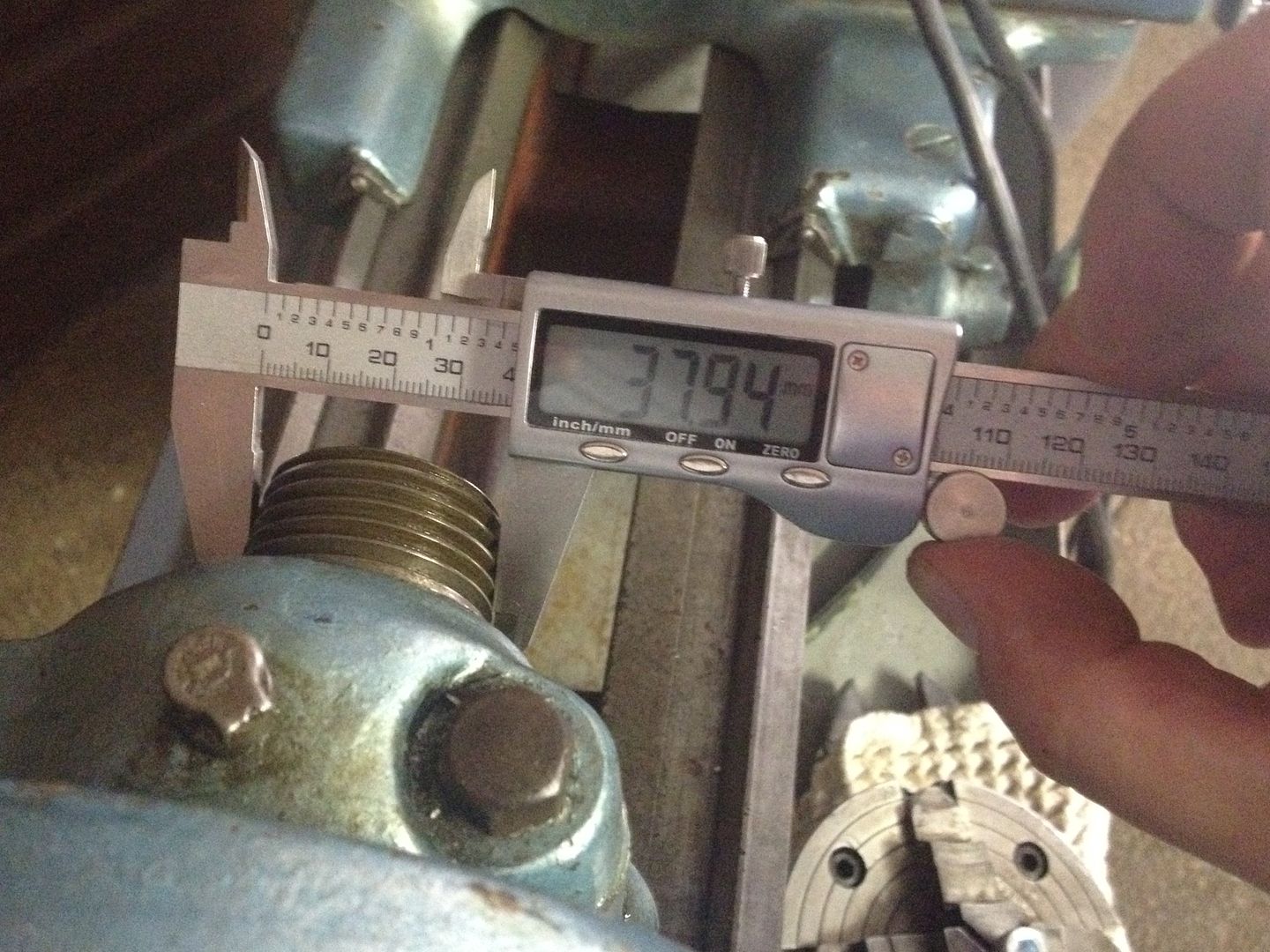
2. Keen to get a 3 jaw chuck. Do I get one with a 38mm spindle? Cannot see anything like that on my searches:
3. What gears an I missing to get the set screw working as it should? Is it possible to retrofit a gearbox to the mechanism to remove the need for changing gears?
Thanks in advance.
-
24th Feb 2014, 08:19 AM #3
Golden Member
- Join Date
- Sep 2009
- Location
- Sydney
- Posts
- 666
Having picture issues. Not sure why they aren't all showing. Tried to clip the posts to max 11 photos but still having some teething problems.
-
24th Feb 2014, 07:26 PM #4
Golden Member
- Join Date
- Nov 2005
- Location
- adelaide
- Posts
- 597
welcome neevo to hercus world
a bit at a time the thread on the chuck spindle will probably be inch and a half x 8 un thread ( not unc)
the nuts on the banjo i think are 1/2 inch unc not whitworth there are spacers and bushes that fit in the gears .
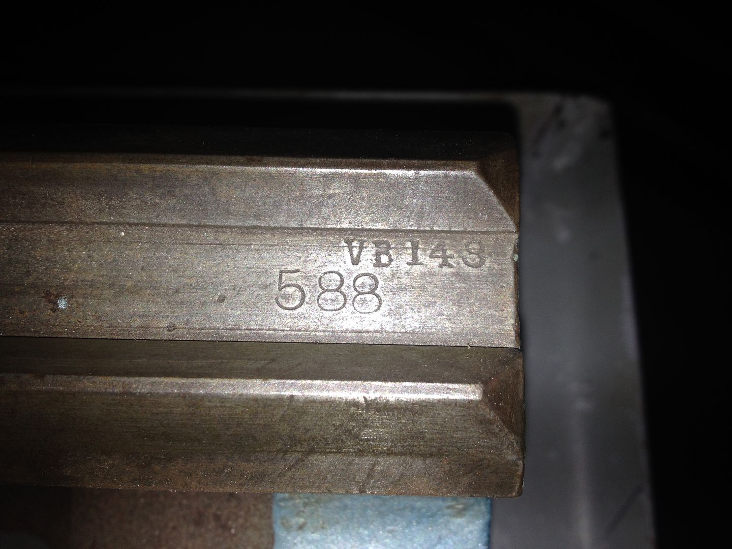
i reckon its a pre 1955s model but if you have a look on the right hand side of the bed between the Vs there should be a number stamped that will give an indication to its age
-
24th Feb 2014, 07:48 PM #5
Golden Member
- Join Date
- Sep 2009
- Location
- Sydney
- Posts
- 666
Lathe Help
Thanks tanii, needless to say I'm pretty happy to have a lathe in the shop. Just need to get it up and running.
Checked out the bed and found the mark you were talking about:
I will look out for a chuck with the thread specs you mentioned. Is it normal to have a new backing plate for each chuck so you only have to screw it on?
Also I've noticed on other Hercus' and South Bends that the adjuster has a lever on it (to release the tension on the drive belt). Am I correct in thinking mine is missing?
BTW I bought a replacement shouldered 1/2 shouldered bolt for the banjo but it was a fraction too large to fit through the gap. I was going to modify it a bit to get it working.
-
24th Feb 2014, 08:02 PM #6
Golden Member
- Join Date
- Sep 2009
- Location
- Sydney
- Posts
- 666
Just been in the Australian Metal Hobbiest site and it turns out I have a Hercus 9" Model C.
-
25th Feb 2014, 10:08 AM #7Tiptoeturtle Guest
"BTW I bought a replacement shouldered 1/2 shouldered bolt for the banjo but it was a fraction too large to fit through the gap. I was going to modify it a bit to get it working."
The correct part is called a compound gear idler bolt on the AMH website, which also sells them. You may need one or two of these (you may need at least one because one original one is missing, perhaps the second original one is missing also, with a ring-in part substituted, I do not know). The bolts use hexagonal nuts, have shallow square heads, one washer and one 5/8" bush / bearing for the compound gears.
Hercus Idler Gear bolt_014.jpg
Congratulations on purchasing what I think is a WW2 veteran Hercus lathe.
-
25th Feb 2014, 11:54 AM #8
Most Valued Member
- Join Date
- Jun 2007
- Location
- sydney ( st marys )
- Age
- 64
- Posts
- 4,890
If you modify the bolt you have it will need to be 7/16 Dia.
Should be UNC but doesn't really mater.
You can fit an A model gearbox.
You will need a lead screw to suit.
You don't need to change the carriage unless you wish to power face, you can just use the half nuts .
-
25th Feb 2014, 12:40 PM #9
Golden Member
- Join Date
- Sep 2009
- Location
- Sydney
- Posts
- 666
Excellent!!! Thanks for that, great info. Originally Posted by Tiptoeturtle

No need to power face but it would be good to have gearbox on power feed. For my understanding it is just the gearbox and a different lead screw? I also assume there is a metric OR imperial box? Isn't that a bit limiting, what if I wanted to do both? Originally Posted by pipeclay
-
25th Feb 2014, 01:20 PM #10
Most Valued Member
- Join Date
- Jun 2007
- Location
- sydney ( st marys )
- Age
- 64
- Posts
- 4,890
If you wished to cut both Metric and Imperial threads on the lathe you have at present,or you wish to add a Quick Change Gearbox you will require the correct Transposing Gears.
If you were able to source a Metric Gearbox and Leadscrew you would also need Metric Half Nuts, and possibly the other associated gears for the basic drive train,the only other thing you would require is the Threading and Feeding Charts for your lathe.
If you were going to the trouble to fit a Quick Change Box of any type the only standard modification you would need to do apart from changing the Leadscrew and Halfnuts would be to replace the 20 tooth stud gear with a 16 tooth stud gear when feeding only and revert back to the 20 tooth gear when threading.
-
25th Feb 2014, 01:30 PM #11
Golden Member
- Join Date
- Sep 2009
- Location
- Sydney
- Posts
- 666
Got it. Thought it would be one or the other. So I assume once you've got metric (with a gearbox on the lead screw) your stuck with that. Originally Posted by pipeclay
I will look at getting the gears and charts as a first step, happy to change gears for thread cutting which is probably going to be the lowest cost option too.
-
25th Feb 2014, 03:17 PM #12
Senior Member
- Join Date
- Jun 2013
- Location
- Tasmania
- Posts
- 257
Just looking at your pictures, your spindle bearings needs their lower oilers. Don't run your lathe dry or you could gall/damage your spindle and bearings.
You could buy them, or just fashion something suitable using brass elbows and some basic covers to get you started. They are called gitts oilers, but can be a little expensive for the real thing, but its not hard to make a suitable replacement. Given they are missing, I'd do the reading up on how to remove your spindle and assess the oiling wicks too. This will give you a look at the state of the spindle and bearing surface and also see how much crud is in the reserviours.
South Bend lathes are basically identical, so a lot of the information out there for the South Bends is directly applicable to the Hercus.
Just work through the steps to get it cleaned up and running then worry about extra bits after that.
Have fun.
-
25th Feb 2014, 03:22 PM #13
Golden Member
- Join Date
- Sep 2009
- Location
- Sydney
- Posts
- 666
Saw a great video on disassembling the spindle the other day. Will do that, check for galling, check condition of the oilers and look to rebuild in a way that is as close to original as possible (functionality wise).
-
25th Feb 2014, 08:59 PM #14
Golden Member
- Join Date
- Sep 2009
- Location
- Sydney
- Posts
- 666
Lathe Help
So good news... and bad

I used this great video to learn how to breakdown the spindle.
http://youtu.be/U1agcVkQ63U
I was keen to clean the lathe prior to using it in anger as it hadn't looked like it had been looked after.
The good news is that I went perfectly. The bad will reveal itself in due course.
First up I loosened the spindle caps:
ImageUploadedByTapatalk1393322142.656524.jpg
Next was to undo the gear covers on the spindle and remove them:
ImageUploadedByTapatalk1393322184.115158.jpg
Had some trouble breaking the threads on the chuck by hand so I used some gentle persuasion using a wrench:
ImageUploadedByTapatalk1393322265.491286.jpg
Next I removed the threaded end piece that takes up the slack on the spindle:
ImageUploadedByTapatalk1393322329.029899.jpg
... And then removed the rear drive gear mechanism so I could remove the threaded end piece:
ImageUploadedByTapatalk1393322393.375399.jpg
-
25th Feb 2014, 09:06 PM #15
Golden Member
- Join Date
- Sep 2009
- Location
- Sydney
- Posts
- 666
Lathe Help
I fashioned a spindle puller using some threaded rod, old decking boards and a fork seal compressor with a bit of tape around it. Worked perfectly:
ImageUploadedByTapatalk1393322474.479939.jpg
ImageUploadedByTapatalk1393322490.351318.jpg
ImageUploadedByTapatalk1393322503.907541.jpg
This is where the bad news comes in. Looks like the felt oilers have long gone on one side, causing damage to the spindle bearing surface and the spindle itself. There are 2 large sections of un damaged surface but not sure if this lathe is toast from this damage, I hope not. It certainly felt smooth and I hope I can clean it up, and get it to a place where the damage has been limited. There aren't any raised sections on the spindle or bearing face but there are deep grooves, hopefully they will just aid in oiling the spindle
Pics:
ImageUploadedByTapatalk1393322704.557518.jpg
ImageUploadedByTapatalk1393322718.796224.jpg
The gear side seems fine despite a groove or two on the bearing surface and spindle:
ImageUploadedByTapatalk1393322766.142252.jpg
The spindle itself:
ImageUploadedByTapatalk1393322785.370459.jpg
ImageUploadedByTapatalk1393322800.641985.jpg


 Reply With Quote


Similar Threads
-
any one recognize this Lathe ? look like quality lathe but no name pictures inside
By thorens in forum METALWORK GENERALReplies: 2Last Post: 15th Jul 2013, 01:24 AM -
SOLD: Lathe for Lathe Drill Mill (Near Liverpool NSW)
By Auskart in forum METALWORK - Machinery, Equipment, MARKETReplies: 9Last Post: 29th Jun 2010, 07:02 PM -
Buying a lathe (Old massive Lathe, or New small C6 Lathe)
By Ch4iS in forum METALWORK GENERALReplies: 5Last Post: 25th Mar 2009, 12:19 PM
