

 Thanks: 0
 Likes:
  Needs Pictures: 0
 Picture(s) thanks: 0
Results 1 to 15 of 34
Thread: Measure twist with a pendulum ?
-
5th Feb 2015, 11:14 AM #1
 Golden Member


- Join Date
- Nov 2010
- Location
- Gippsland Victoria
- Posts
- 733
 Measure twist with a pendulum ?
Hello,
Was just reading the thread about lathe levels. Posted this separately to avoid mucking up the original thread.
I've seen some articles posted on internet about making big pendulums that sit on the lathe bed that can measure twist. There are a couple of u-tube videos as well. A thread was posted here a couple of years back.
It looks relatively simple and am wondering why I dont see it discussed and used more often - are there big problems with this pendulum method ?
Bill
-
5th Feb 2015, 11:36 AM #2
Most Valued Member
- Join Date
- Jul 2010
- Location
- Melbourne
- Posts
- 9,088
Because most believe its not "close enough".
Now if your pendulum was long enough it would be "close enough". Take 0.02mm/m division of a level as a starting point, with the divisions 3mm a part. If you had a pendulum 5 meters long that would give you
1. movement of 0.1mm, 1/30 the movement of the bubble in the level, so we better make the pendulum 50m long, that will give you a full 1mm of movement, still 1/3 of what the level gives you, but I'll call that "close enough".
2. a hole in your roof .
.
Then you just have to make it repeatable...now thats going to be the tricky part.
Sure makes a level look pretty easy.
Stuart
p.s hope my maths is right
-
5th Feb 2015, 11:52 AM #3
Diamond Member
- Join Date
- Feb 2013
- Location
- Laidley, SE Qld
- Posts
- 1,039
Theoretically a pendulum will work. I see it coming down to the practicality of how tall a pendulum (and its support structure and stiffness/reliability/repeatability thereof) will be needed to accurately measure the twist in the ways.
A 1m long pendulum is going to move 4.36mm for .25° twist., hopefully you are only chasing a tiny fraction of that .25°.
EDIT Stustoys thinks and types faster than I do
-
5th Feb 2015, 12:00 PM #4
Most Valued Member
- Join Date
- Jul 2010
- Location
- Melbourne
- Posts
- 9,088
I should add there is nothing wrong with the pendulum idea. Its just reading the movement to the required level of accuracy and as I said repeatability.
Now all of these DIY ones I have seen use a solid pendulum, thats going to make the bearing at the top tricky. Get rid of that and use wire instead. Add dampening with some oil. Add optics so your pendulum doesn't need to be stupidly long. Better yet add transducers(?) and read it electronically and you have a level capable of being "more than close enough". Or you could ask RC(?) if you can borrow his
Stuart
EDIT but Bob gets all his thoughts in one post
EDIT 2 Having done all the above this is what you end up with. http://www.woodworkforums.com/showthread.php?t=189200&
-
5th Feb 2015, 12:09 PM #5
Pink 10EE owner
- Join Date
- Aug 2008
- Location
- near Rockhampton
- Posts
- 6,218
No Stuart... simply no...
-----------------------------------------------------------------------
Pendulums will not work, it is not even worth putting your brain cells into thinking about it... You would need sapphire bearings to start with to cut down on friction, and my thinking ended there...
Precisions levels are dirt cheap these days, not like in the 1990's and before...Gold, the colour of choice for the discerning person.
-
5th Feb 2015, 12:12 PM #6
Most Valued Member
- Join Date
- Jul 2010
- Location
- Melbourne
- Posts
- 9,088
Of course they will...... you've got one! Originally Posted by .RC.

Though I doubt you'd let me borrow it
Stuart
-
5th Feb 2015, 01:02 PM #7
Most Valued Member
- Join Date
- Jun 2008
- Location
- Victoria, Australia
- Age
- 74
- Posts
- 5,080
Speaking of alternatives to bubbles... Last year, I designed an electronic level. I based the design on the SCA103T series MEMS inclinometers. You could build one with adjustable sensitivity for less than $200.

Easier than a 50m pendulum.
Ray
PS Datasheet here .. http://www.muratamems.fi/sites/defau...261700a3_0.pdf
-
5th Feb 2015, 02:32 PM #8
Retired
- Join Date
- Jan 2015
- Location
- in transit
- Posts
- 42
Bearings?
I don't know why you would use bearings. You wouldn't use bearing in balancing a crankshaft (statically), you'd use knife edge rollers. Same principle could be used in a 50m pendulum. Then you could add optics, lasers, transducers, oil dampening whatever you like, it would be a thing of great beauty and you could admire it from three klms away. Problem would be where to store the pendulum when not in use. I think building a 50m high pendulum with all the associated support structures to keep it rigid might work out a tad expensive though.
-
5th Feb 2015, 02:59 PM #9
Most Valued Member
- Join Date
- Jun 2008
- Location
- Victoria, Australia
- Age
- 74
- Posts
- 5,080
Taking another approach, suppose you use DTI's to measure the pendulum position, Imagine two DTI's set up on opposite sides of a heavy bar pendulum, you can measure 0.01 with the DTI easily enough, so to get 0.05mm/meter you would only need a pendulum 200mm long.. Some sort of knife edge pivot, like they use in scales. Originally Posted by Stustoys
Might be doable?
Ray
-
5th Feb 2015, 03:11 PM #10
Most Valued Member
- Join Date
- Jul 2010
- Location
- Melbourne
- Posts
- 9,088
What do the rollers turn on? Originally Posted by casjon
Though really a 50m pendulum isn't likely to need a bearing, I'm guessing even if it was fixed at the "pivot" it would flex enough to cover the range required. So that's one problem solved
Stuart
-
5th Feb 2015, 03:46 PM #11
Most Valued Member
- Join Date
- Jul 2010
- Location
- Melbourne
- Posts
- 9,088
Its going to cost you for the DTI's than a level Originally Posted by RayG

Knife edges worry me a little repeatability wise. If its a true knife edge I dont see how you can locate it. If it has a radius it moves the opposite way, if you put it in a V it now has to slide. (though lets face it they must have this worked out for scales. but to what level I dont know)
If I had to guess I'd say there is going to be a lot of hyst..... something or other(cant remember the word. lag for lack of a better word) as I think you're effectively "measuring" the weight of part of the pendulum and there is a fair difference between with I call the "up weight" and the "down weight" of a DTI. Whether this would be enough to be a issue in this case I'm not sure, but it can make a huge difference on a soggy noodle stand. If I recall correctly in my tests it was as bad as 0.005" so the DTI is sitting there saying "nothing has moved" when its really moved 0.005" just that the difference in "read weights" means the deflection of the stand has changed but the needle hasn't moved. (does any of that make sense? lol) Now having two DTIS might cancel most of that... not so sure.
Stuart
p.s that's a nifty little chip. 0.001°=0.02mm/m right?
-
5th Feb 2015, 05:17 PM #12
Most Valued Member
- Join Date
- Jun 2008
- Location
- Victoria, Australia
- Age
- 74
- Posts
- 5,080
Hi Stuart,
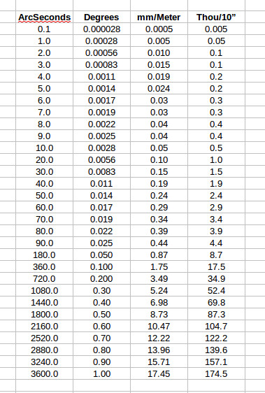
I did a speadsheet for converting angles into different units, when I was looking at that chip...
As far as the forces go, you don't really need 2 DTI's, all that's needed is a clever way of attaching one..
If you can find an old Toledo shop scale they had a knife edge setup..
Like this..
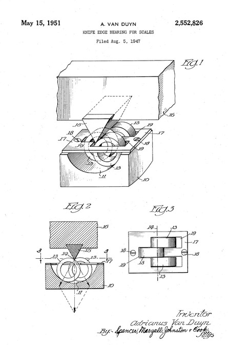
Ray
-
5th Feb 2015, 06:07 PM #13
Retired
- Join Date
- Jan 2015
- Location
- in transit
- Posts
- 42
Knife edges
Forget rollers, have the pendulum knife edge resting between two like edges set at 90 degrees to the pendulum edge = no friction. I like the DTI idea, but wouldn't the pressure from the DTI have an effect on the movement of the pendulum? particularly if the pendulum were only 200mm long?
-
5th Feb 2015, 06:10 PM #14
Most Valued Member
- Join Date
- Jul 2010
- Location
- Melbourne
- Posts
- 9,088
Hi Ray,
You can even drop it 1m onto concrete and it should be ok,, try that with your bubble level
I don't think that helps. To use some figures I made up because I cant recall the real ones. Lets say when the pendulum is swinging towards the DTI the "weight" required to move the needle of the DTI is 50g. Now when the pendulum starts to to move the other way the needle wont start to move until the "weight" is down to 40g. So what ever the deflection of the pendulum is for 10g is a dead zone you will know nothing about.* Originally Posted by RayG
Now who can do the maths on how far a pendulum of a given length and weigh moves for a given load? My guess is it s fair bit when the pendulum is vertical. less and less as it moves further but by then its all over of our usage.
Stuart
*I'm on the way out to the shed soon I'll come up with the real"ish" numbers.(though I'm not sure anyone else cares lol)
-
5th Feb 2015, 06:44 PM #15
Most Valued Member
- Join Date
- Jul 2010
- Location
- Melbourne
- Posts
- 9,088
Some days I have to much time on my hands
Cheapie 0.01mm 9.8g "up" 7.1g "down"
Compac 0.0005" 14 "up 9.3 "down"
Compac 0.0001" 22.5 "up" 10.2 "down"
Stuart

 Reply With Quote
Similar Threads
-
Pendulum Level
By tongleh in forum METALWORK GENERALReplies: 29Last Post: 31st Aug 2012, 09:42 PM
