

 Thanks: 0
 Likes:
  Needs Pictures: 0
 Picture(s) thanks: 0
Results 1 to 15 of 29
Thread: Making a sine plate
-
25th Nov 2013, 11:48 PM #1
 Blacksmith, Cabinetmaker, Machinist, Messmaker


- Join Date
- Dec 2011
- Location
- Canberra
- Age
- 40
- Posts
- 4,515
 Making a sine plate
Hi all,
I made a start on my 450x150 sine plate today. Pretty much just got the 2 main plates ground flat. Took a long time, especially since the grinder decided to slow down.....not the sort of thing you notice when it happens slowly. All of a sudden it just stopped..... turned out the soft return valve had vibrated loose and eventually come right out!
Anyway, the plates are flat better than .0005", well either that or the headstone is up the creek!
Not much to show really, the plates and the 5/8" silver steel i will use for the rolls, and a pic of some musings over which way to mount the rolls.
Cheers,
Ew1915 17"x50" LeBlond heavy duty Lathe, 24" Queen city shaper, 1970's G Vernier FV.3.TO Universal Mill, 1958 Blohm HFS 6 surface grinder, 1942 Rivett 715 Lathe, 14"x40" Antrac Lathe, Startrite H225 Bandsaw, 1949 Hercus Camelback Drill press, 1947 Holbrook C10 Lathe.
-
26th Nov 2013, 01:34 AM #2
Most Valued Member
- Join Date
- Jun 2008
- Location
- Victoria, Australia
- Age
- 74
- Posts
- 5,080
Hi Ewan,
I could take some pictures of the Omer Robbins compound sine table mechanism.. if you are interested.
Hang about... I found some I took a while back..
Regards
Ray
-
26th Nov 2013, 04:04 AM #3
Intermediate Member
- Join Date
- Apr 2013
- Location
- San Diego
- Posts
- 28
Here's how I made mine.
Gene
-
26th Nov 2013, 09:32 AM #4
Blacksmith, Cabinetmaker, Machinist, Messmaker
- Join Date
- Dec 2011
- Location
- Canberra
- Age
- 40
- Posts
- 4,515
Ray, When i was searching for idea's that hinge type was exactly what i decided on. Good to have some decent pics of them though. I was going to put mu hinges on the ends of the bottom plate, a SHCS and a pair of dowels. That plate must be pretty tall, it looks far more complicated than they need to be, i guess it would be very rigid though.
Gene, your plate looks really good, how did you machine the grooves for the rolls to sit in? They look like they are done with a bull nose endmill?
Cheers,
Ew1915 17"x50" LeBlond heavy duty Lathe, 24" Queen city shaper, 1970's G Vernier FV.3.TO Universal Mill, 1958 Blohm HFS 6 surface grinder, 1942 Rivett 715 Lathe, 14"x40" Antrac Lathe, Startrite H225 Bandsaw, 1949 Hercus Camelback Drill press, 1947 Holbrook C10 Lathe.
-
26th Nov 2013, 11:34 AM #5
Blacksmith, Cabinetmaker, Machinist, Messmaker
- Join Date
- Dec 2011
- Location
- Canberra
- Age
- 40
- Posts
- 4,515
Hi Ray,
I was just wondering how your plate locks? Do you leave the blocks in and just lock the hinges or does it have a clamp type arrangement that holds the plates together, clamping the blocks in place?
Cheers,
Ew1915 17"x50" LeBlond heavy duty Lathe, 24" Queen city shaper, 1970's G Vernier FV.3.TO Universal Mill, 1958 Blohm HFS 6 surface grinder, 1942 Rivett 715 Lathe, 14"x40" Antrac Lathe, Startrite H225 Bandsaw, 1949 Hercus Camelback Drill press, 1947 Holbrook C10 Lathe.
-
26th Nov 2013, 12:14 PM #6
Most Valued Member
- Join Date
- Jul 2010
- Location
- Melbourne
- Posts
- 9,088
Hi Ewan,
In case you havent already come to the same conclusion I like the top sketch better. You can play around on the grinder for as long as it takes the get the distance right*. The bottom one, once its to small its to small and you'd have to start over. It also means the bolts arent doing much.
Keep the pictures coming. Should be finished sometime this afternoon right?
Stuart
*as long as you leave the silver steel a little longer than the table for the minute to make measuring easier.
-
26th Nov 2013, 12:37 PM #7
Blacksmith, Cabinetmaker, Machinist, Messmaker
- Join Date
- Dec 2011
- Location
- Canberra
- Age
- 40
- Posts
- 4,515
Grinding edges right now.....I really could do with an auto downfeed.
It's amazing how you miss the simple things. I like the top design better too, but couldn't think for the life of me how to measure it accurately. of course I can measure over the rolls. Anyway, this edge is done, wheel dressing time.....
Ew1915 17"x50" LeBlond heavy duty Lathe, 24" Queen city shaper, 1970's G Vernier FV.3.TO Universal Mill, 1958 Blohm HFS 6 surface grinder, 1942 Rivett 715 Lathe, 14"x40" Antrac Lathe, Startrite H225 Bandsaw, 1949 Hercus Camelback Drill press, 1947 Holbrook C10 Lathe.
-
26th Nov 2013, 01:28 PM #8
Most Valued Member
- Join Date
- Jun 2008
- Location
- Victoria, Australia
- Age
- 74
- Posts
- 5,080
Hi Ewan, Originally Posted by Ueee

Just the hinge locks, but we did have it move once when it was on the mill, never had a problem on the grinder. Personally I'd prefer a locking strap that you lock down after you set the gage block.
Just a idea, if you make the distance 10" and all the standard sine tables will work. ( 10" and 5" seem to be common distances..)
Regards
Ray
-
26th Nov 2013, 02:37 PM #9
Diamond Member
- Join Date
- Mar 2011
- Location
- Dural NSW
- Age
- 82
- Posts
- 1,203
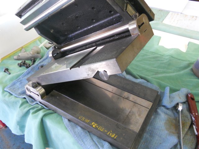
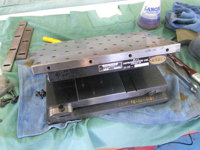
Sine Plate
Here is a Sine Plate I made back in 1961.
Its a 4" precise centre on the rollers.
Made from mild steel case hardened & ground, the rollers were made from tool steel hardened & cylindrical ground.
The pivot hole or hinge point was internally ground, on a machine at Sydney Tech during my course there.
Clamping is by a hardened & ground, circular plate on the end of the hinge point, using an "Allen Key". The setting is then braced if required by a side stay & Allen screws. This makes it very secure.
Very handy for use on the surface grinder, have used it to grind a lot of 25 degree woodworking plane blades, as well as many other uses.
Hope this is of interest.
regards
Bruce
-
26th Nov 2013, 03:33 PM #10
Pink 10EE owner
- Join Date
- Aug 2008
- Location
- near Rockhampton
- Posts
- 6,218
I would measure it over the rolls by placing it against a known good master square on a surface plate, so it sits vertically.... Then using gauge blocks and something like a height gauge with an indicator (to act as a comparator) on it stack the blocks until you get the same height at the first reading... Originally Posted by Ueee
Note the stack dimensions, stack a new height until you get the second dimension.... One minus the other is the distance, and go from there to work it out...Gold, the colour of choice for the discerning person.
-
26th Nov 2013, 03:55 PM #11
Most Valued Member
- Join Date
- Oct 2010
- Location
- melbourne, laverton
- Posts
- 1,910
good one
g'day bruce thanks for that.;looks like a kuta handy tool.
the longitudinal lines in the bottom piece are they just there for
less grinding or for clearance?
aaron
-
26th Nov 2013, 04:29 PM #12
Intermediate Member
- Join Date
- Apr 2013
- Location
- San Diego
- Posts
- 28
All the components except for the rolls are made from AISI O-2 steel, hardened to Rockwell C60-61. Tempered and then surface ground. The grooves for the rolls are ground from solid. No need to machine first. Originally Posted by Ueee
The rolls were made from D-3 steel also heat treated and ground.
There is no need to have an exact distance between centers of the rolls. You can of course have them a precise even distance if you wish. All that is necessary is that you know what the measurement is. That's why we have calculators.
Gene
-
26th Nov 2013, 04:51 PM #13
Blacksmith, Cabinetmaker, Machinist, Messmaker
- Join Date
- Dec 2011
- Location
- Canberra
- Age
- 40
- Posts
- 4,515
I had thought of something similar, but using my dial height gauge. My bigger gauge blocks are still at the Gardiner testing laboratory. The thing I don't like about doing it this way is it means removing the plate from the grinder and loosing my......no it doesn't, put it agains the back rail you moron! Originally Posted by .RC.
Ignore all that, hey Josh, you done those gauge blocks yet?
Cheers,
Ew1915 17"x50" LeBlond heavy duty Lathe, 24" Queen city shaper, 1970's G Vernier FV.3.TO Universal Mill, 1958 Blohm HFS 6 surface grinder, 1942 Rivett 715 Lathe, 14"x40" Antrac Lathe, Startrite H225 Bandsaw, 1949 Hercus Camelback Drill press, 1947 Holbrook C10 Lathe.
-
26th Nov 2013, 05:14 PM #14
Diamond Member
- Join Date
- Mar 2011
- Location
- Dural NSW
- Age
- 82
- Posts
- 1,203
Longitudinal Lines
Aaron Originally Posted by azzrock
Thanks for your interest.
The longitudinal lines were ground with a narrow wheel on a surface grinder to reduce the surface area in lapping that particular area flat.
It was a bit excessive, & more of a "cosmetic" thing, not really required, but it did reduce the time taken to lap the section that makes contact with the gauge blocks.
A surface ground finish would have been more than adequate.
regards
Bruce
-
26th Nov 2013, 05:35 PM #15
Most Valued Member
- Join Date
- Oct 2010
- Location
- melbourne, laverton
- Posts
- 1,910
ah
lapping i didnt even think of that. i just assumed it would be surface ground.
i think thats a tool that deserves a very nice wood box.
next time i run into one on my rounds i think i might add it to the
collection.


 Reply With Quote
Similar Threads
-
Sine bar setting taper attachment
By Retromilling in forum METALWORK GENERALReplies: 24Last Post: 3rd Nov 2013, 07:54 AM -
Sine bar errors article
By morrisman in forum METALWORK GENERALReplies: 0Last Post: 21st Sep 2012, 04:30 PM -
Sine Bars
By Ueee in forum METALWORK GENERALReplies: 3Last Post: 30th Aug 2012, 11:26 PM -
A Delicacy from Placentia - Kingmann White MINI-SINE Bar
By Anorak Bob in forum METALWORK GENERALReplies: 6Last Post: 11th Aug 2012, 08:57 PM
