

 Thanks: 0
 Likes: 0
 Needs Pictures: 0
 Picture(s) thanks: 0
Results 1 to 15 of 34
Thread: Star/Delta motor wiring
-
23rd Feb 2012, 08:12 PM #1
 Pink 10EE owner


- Join Date
- Aug 2008
- Location
- near Rockhampton
- Posts
- 6,218
 Star/Delta motor wiring
ADDED BY ADMIN
DISCLAIMER
No liability is accepted by UBeaut or the Wood Working Forum's administrators
or moderators for advice offered by members posting replies
or asking questions regarding electrical work.
We strongly advise contacting a Licensed Tradeperson for all electrical work.WARNING
Information supplied within posts is not to be considered as detailed formal instructions to complete a task.
Members following such information do so at their own risk
With my little TC grinder I finally bought a VFD for it so I can run it off 240V plus can run it faster for the smaller grinding wheels..
A plate on the side of the grinder gives directions for wiring for 208V or 415V, as well under the electrical plate on the motor gives directions for "high" voltage and "low" voltage..
However there are only three wires coming out of the motor to the terminal block...
I have pulled the motor apart and think I have found three wires twisted together.. I assume this is the centre point for the Wye winding and I will need to unsolder those wires and bring them out to the terminal block.. To wire in Delta...
Does that sound right?

 Gold, the colour of choice for the discerning person.
-
23rd Feb 2012, 08:49 PM #2
Golden Member
- Join Date
- Mar 2009
- Location
- Melbourne
- Age
- 54
- Posts
- 825
G'day RC,
That looks like it.
Best way to test is to dissconnect them then using you digital multimeter (I think that's one I see in your pic) measure the resistance between each wire and its partner terminal (the other end of each coil will be connected to one of the three terminals)
If that is the common point of the star then the reading should be the same for each coil (typically around 9 ohms for a 4 pole motor).
A handy tip to remove the shelac coating is to heat the end of the wire with a lighter to burn off the coating then give it a rub with steel wool.
Cheers,
Greg.
-
23rd Feb 2012, 09:22 PM #3
Just some guy.
- Join Date
- Jul 2003
- Location
- The Fabulous Gold-plated Coast.
- Age
- 69
- Posts
- 2,251
It depends...the terminal block may have nine terminals and some joiner links. The joiners are configured per the diagram.
It's all part of the service here at The House of Pain
-
23rd Feb 2012, 09:38 PM #4
 I break stuff...
- Join Date
- Aug 2010
- Location
- Toorloo Arm, VIC
- Age
- 39
- Posts
- 1,297
But if there are only 3 wires coming out, wouldn't that suggest the motor is permanently wired in star config? In which case I would have thought that changing the joiner blocks around would cause some quantity of smoke to escape. Originally Posted by Greg Q

However, I will freely admit that I'm pretty fuzzy on the details of 3 phase and motors. I was under the impression that the change from star to delta was a requirement to get from 415v 3 phase to 240v 3 phase for some reason which I can't remember.... Hopefully I'll learn something new in this thread!
Your photo certainly looks like the star point I found in my mill motor, I'd agree with Kwijibo that you seem to have found it. Originally Posted by .RC.
-
23rd Feb 2012, 09:40 PM #5
Most Valued Member
- Join Date
- Jul 2010
- Location
- Melbourne
- Posts
- 9,088
I dont understand the wiring diagram. It looks to me in be wired in star in "low voltage" and delta in "high voltage"(which as I understand it is backwards to most motors).................. anyone care to explain?
Stuart
p.s. how may hp is the motor RC?
p.p.s. what rpm?Last edited by Stustoys; 23rd Feb 2012 at 09:47 PM. Reason: ps+pps
-
23rd Feb 2012, 09:56 PM #6
Golden Member
- Join Date
- Mar 2010
- Location
- Nth Qld
- Posts
- 687
So there's only 3 external wires even though it has the sticker for a basic nine wire dual voltage motor?. If it was a nine wire you may have wires labelled according to the sticker internally which is what my Baldor had when I rewired it for lower voltage.
Otherwise that three wire connection must be the star connection and you can disconnect all three from each other and check with a multimeter on low ohms setting to get each of the three windings.
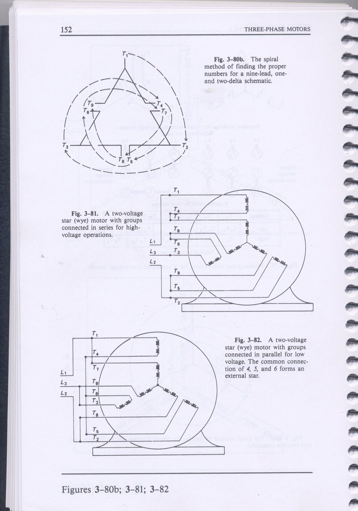
To get the lower voltage for a nine wire motor each phase has two windings and you end up with two sets of star connected, 3 phase windings in parallel. The stars are not connected together but the line connections are which is something I'd never seen before in a 3 phase motor.
So in a nine wire motor, you have two sets of 208V star windings each at half the total rated current which are then paralleled to give full rated motor power.
Edit: so for the windings you do have, you'll have to connect as "delta" to get 240V operation. Attached below is the nine wire arrangement I had with my Baldor 2Hp to get 230V operation.
-
23rd Feb 2012, 09:57 PM #7
Most Valued Member
- Join Date
- Aug 2010
- Location
- Near Bendigo, Victoria, AUS
- Age
- 72
- Posts
- 3,105
RC - that motor has been rewound. Nothing on the label or connection diagram is of relevance. At 208V it would have been made for Canada and maybe didn't survive running on 240V. When it was rewound, they saved some effort by wiring it for Australian common 415V 3-phase mains connection.
Joe
-
23rd Feb 2012, 09:59 PM #8
Pink 10EE owner
- Join Date
- Aug 2008
- Location
- near Rockhampton
- Posts
- 6,218
I wonder if it is a typo or not...
The picture on the machine contradicts the picture on the terminal cover... I think the motor ia 1/3hp, 3000rpm so a single pole...
 Gold, the colour of choice for the discerning person.
-
23rd Feb 2012, 10:03 PM #9
Golden Member
- Join Date
- Mar 2009
- Location
- Melbourne
- Age
- 54
- Posts
- 825
From what RC describes with only three wires coming out of the motor and the look of the yellow insulation I suspect this motor has been permanantly converted to 415 star winding at some stage after its manufacture.
A nine terminal motor is usually a star wound motor which can be configured to run on either a higher or lower 3 phase voltage (208 or 415 in the case of this motor) .
If the links are connected as per the low voltage configuration then only the three coils wound for the lower voltage will be connected to power. If the links are configured for high voltage then an additional coil is series connected to each segment so as to handle the higher voltage.
-
23rd Feb 2012, 10:17 PM #10
Pink 10EE owner
- Join Date
- Aug 2008
- Location
- near Rockhampton
- Posts
- 6,218
I have pulled the wires apart, resistance is 21-22 ohms per winding
It may have been changed after manufacture... It is an ex-govt machine and I am the third owner, it has seen next to no use though..., perhaps it was incorrectly wired for 415V when new and when connected to 415V the magical smoke got released necessitating a rewind...Gold, the colour of choice for the discerning person.
-
23rd Feb 2012, 10:26 PM #11
Most Valued Member
- Join Date
- Jun 2008
- Location
- Victoria, Australia
- Age
- 74
- Posts
- 5,080
Hi .RC,
What I think you've got is as Graziano suggested is a nine wire dual voltage set up... but it might be irelevant if it's been rewired as Joe said for 415v star..
Seperate the star point and bring out the 3 wires, make sure to seperate and insulate securely.. you should find 3 sets of coils, with 3 wires per coil (if they are still there), the tapping on the windings can be ignored, and wire the outside tappings as delta. That should be 240V 3 phase.
I'll try and find the relevant diagrams in Rosenberg, hopefully that will make more sense..
ok here is the 9 wire dual voltage, this is probably what it was originally..
Regards
Ray
-
24th Feb 2012, 09:00 AM #12
Pink 10EE owner
- Join Date
- Aug 2008
- Location
- near Rockhampton
- Posts
- 6,218
Motor winding image
 Gold, the colour of choice for the discerning person.
-
24th Feb 2012, 10:32 AM #13
Golden Member
- Join Date
- Mar 2010
- Location
- Nth Qld
- Posts
- 687
If there's only six wires, disagreeing with the label then it would have to have been rewound at some stage to give three sets of windings like JHovel and Kwijibo said.
The three internal wires would then make it star connected for 415V. All you can do at this stage is bring the six yellow wires out of the motor case and reassemble the motor, then connect the windings in delta form to get a 240V three phase motor.
You'll need to get some spaghetti tube from an electrical shop to cover the three extra wires/joins where you bring out the three wires from what was the original star connection, heatshrink or electricians tape is not really good enough due to vibrations, some sort of high temp woven electrical spaghetti slid over the top of some heatshrink over the soldered connection will do the trick. A non synthetic string like cotton string would be preferred to tie the joins to the windings as hot windings can melt synthetic strings or cable ties and make them let go when very hot like a temporary overload.
-
24th Feb 2012, 08:00 PM #14
Most Valued Member
- Join Date
- Aug 2010
- Location
- Near Bendigo, Victoria, AUS
- Age
- 72
- Posts
- 3,105
I agree with Graziano. This is a 4 pole 1440rpm winding with just three sets of coils. You can (well, I can) see them all and their connections. Definitely 415V star (wye) wired. All you can do it split the 'centre' and bring those wires out to run it in delta on 240V off a VDS.
The beauty is that you found the centre point. SO it;s quite simple. My lathe motor is the same but I can't find the centre point..... it must be tucked under somewhere.
Joe
-
25th Feb 2012, 04:15 PM #15
Senior Member
- Join Date
- Dec 2011
- Location
- South East Queensland, Australia
- Posts
- 355
Hi guys, new here.
Just mentioning
Hopefully, whoever rewound the motor has labeled the three wires that came out of the motor U1, V1, W1, (or alternately A, B, C) so that the winding sequence can be hooked up correctly. If they are labeled you will be able to identify U2, V2, W2 (or A1, B1, C1) so you can get the correct sequence.
If the sequence is wrong the current draw will be high.
If U1, V1, W1 are not labeled then a motor re-winder will be able to identify them for you.
For Delta connection, join U1 to W2; V1 to U2; W1 to V2. Connect each input line to each one of those pairs.
Alternative Delta connection is U1 to V2; V1 to W2; W1 to U2. Connect each input line to each one of those pairs.
Very good that the motor re-winder left the star point so easily accessible.
Cheers.
If I'm not right, then I'm wrong, I'll just go bend some more bananas.

 Reply With Quote


Similar Threads
-
Wiring of a single phase motor.
By krisfarm in forum METALWORK GENERALReplies: 27Last Post: 28th Oct 2010, 08:10 PM -
Have I found the star point of this motor?
By Jekyll and Hyde in forum METALWORK GENERALReplies: 9Last Post: 12th Aug 2010, 11:25 PM -
motor wiring diagram
By .RC. in forum METALWORK GENERALReplies: 2Last Post: 12th Jul 2010, 07:37 PM
