

 Thanks: 0
 Likes: 0
 Needs Pictures: 0
 Picture(s) thanks: 0
Results 1 to 6 of 6
-
1st Oct 2018, 10:52 PM #1
 Intermediate Member


- Join Date
- Nov 2015
- Location
- Adelaide
- Posts
- 27
 Attention CIGweld transtig 150 and 275 owners
Hey Forum members.
just wondering for those forum members who own a CIGweld transtig 150 and also the 275 AC/DC units, if you could possibly get a photo of the electronic control board behind the front panel, im particullary interested in seeing behind the front control panel of the 275 unit, if you can get plenty of photos and also of the part numbers on the board that would be greatly appreciated.
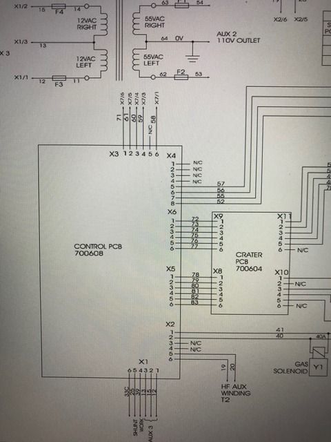
i have been doin abit of reasearch and it almost appears that the transtig 150 i currently own and also another unit that i have on loan both have the main control board out of a transtig 275 machine, i noticed on the pdf for the 275 machine the part number is 700608, the same part number is on my main board (as per on the pdf on this thread //metalworkforums.com/f160/t189...275-series-2-a) it also looks like on this control board there is a spot for one extra potentiometer to be soldered in the same spot as the AC balance knob that the 275 machines run, so if possible it may simply be a case of installing that potentiometer and having AC balance control on the 150 machine!!!
also while browsing through google on noticed on token tool room website his transtig 150 has a different looking control board to the ones I have in my possession https://www.tokentoolroom.com/cig-transtig-180-cigweld/ which has got me really curious as to whats goin on, maybe CIGweld decided to use the 275 control board in the 150 units!!!
pictures to be uploaded so you can get a better under standing.
thanks
MondoLast edited by RVK355; 1st Oct 2018 at 11:15 PM. Reason: changed thread title
-
1st Oct 2018, 11:13 PM #2
Intermediate Member
- Join Date
- Nov 2015
- Location
- Adelaide
- Posts
- 27
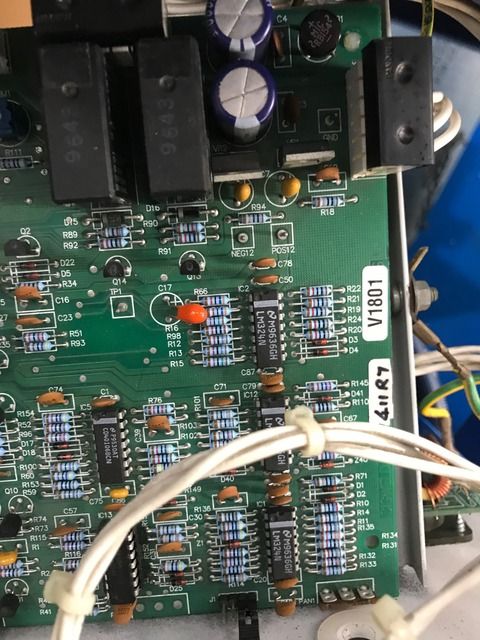
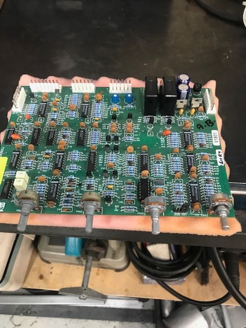
transtig 275 control board PCB #700608
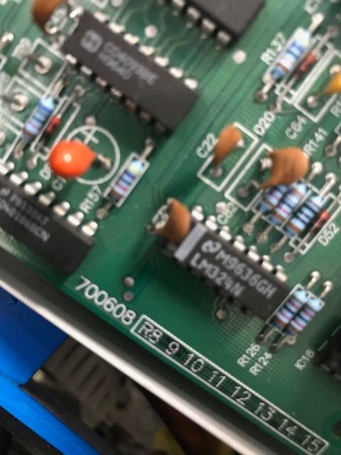
the control board on my transtig 150 same part number #700608
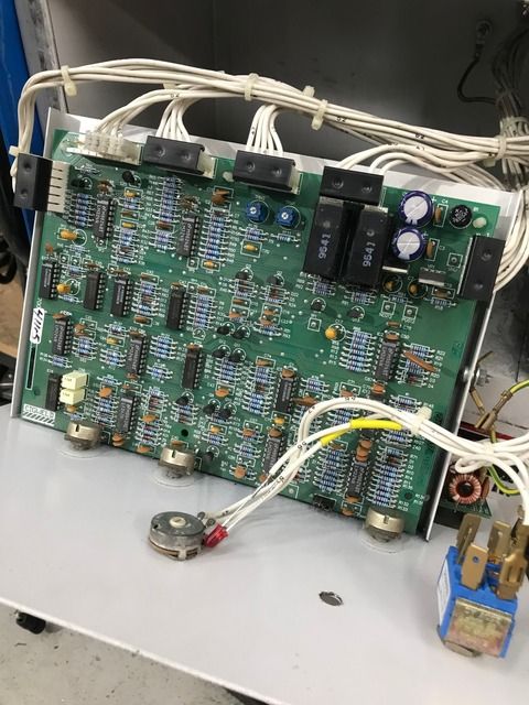
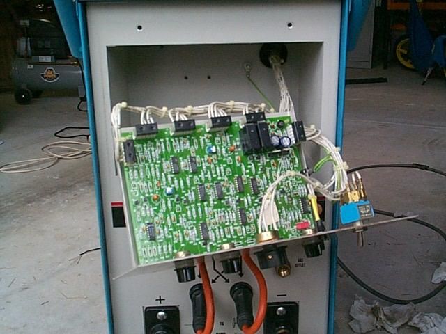
picture of the main control board inside my transtig 150
picture from token tool room of this main control board inside his transtig 150 (note the different layout of the pcb and lack of chips)
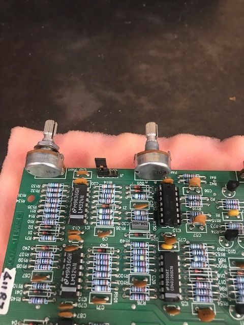
now this picture shows the spot where the 3 pins of a potentiometer would get soldered in (bottom middle of the picture)
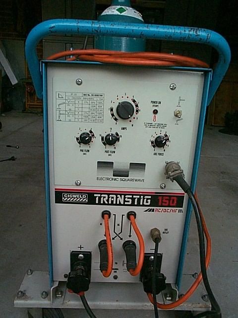
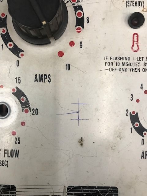
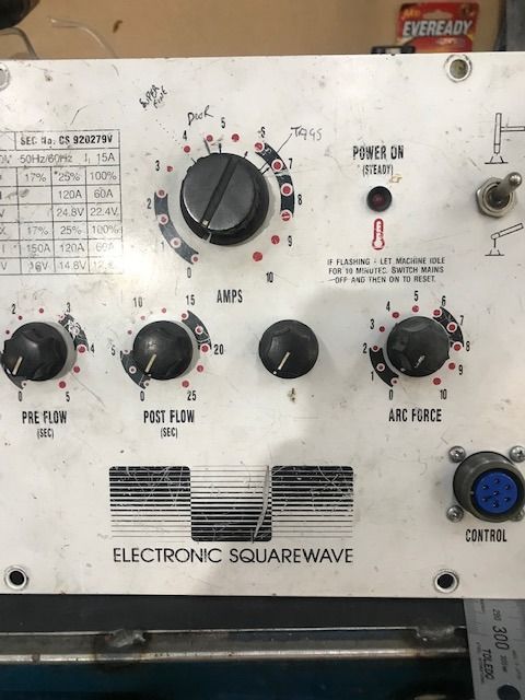
the front control panel of a 150
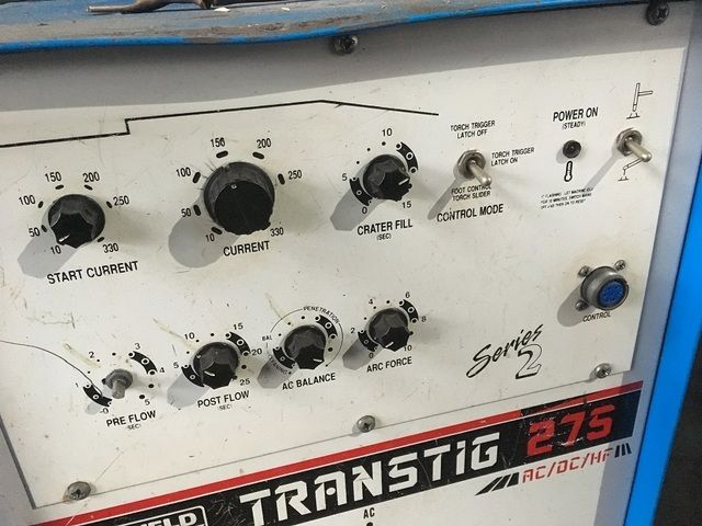
front control panel of the 275, note the position of the AC balance knob, similar spot to the position of the spare potentiometer spot on the previous picture posted up
-
11th Oct 2018, 10:19 AM #3
 Super Moderator
- Join Date
- Jan 2004
- Location
- Mackay North Qld
- Posts
- 6,446
It is quite possible that Token Tools being a manufacturer and repairer of their own welders could have used a diffrerently sourced PCB. Pete is a electrician turned Electrical Engineer with a background in welders and their design.
Why not ring Pete and ask him? He is very easy to get on with.
Grahame
-
13th Oct 2018, 02:01 PM #4
Intermediate Member
- Join Date
- Nov 2015
- Location
- Adelaide
- Posts
- 27
I know he posts on this forum from time to time and was hoping he might chime in. Originally Posted by Grahame Collins

going by the post on his website, don't think he has put in a different sourced board in his 150 transtig as it was a post showing him pull the covers off the machine to have a look inside of the machine.
-
16th Dec 2018, 12:26 PM #5
Intermediate Member
- Join Date
- Nov 2015
- Location
- Adelaide
- Posts
- 27
Just to follow up on this, i spoke with a guy by the name of Geoff from circuts unlimted who has been fixing these PCBs for year and knows them very well.
what has happened is cigweld had done small modifications to the pcbs and changed things through out the years of production, why no idea why he reckons more then likely another engineer would try add his own touch or modification to the board, the PCB is rather complex and complicated, to complicated for what it has to do and could of been a lot more simple, the boards are literally the same in both machines 150 and 275, besides the AC balance control,
-
16th Dec 2018, 01:04 PM #6
Intermediate Member
- Join Date
- Nov 2015
- Location
- Adelaide
- Posts
- 27
Transtig 150 AC balance control modification
Ok as per some of the information provieded about the PCB boards, it seems the control board on the transtig 150 can be made to have AC balance control.
I have done this to my transtig 150 and tested it out, it deffinatly does work and can notice it when welding when you adjust the ac balance knob from one side to the other side, please note that in the transtig 275 user manual it does comment about the effect on the duty cycle when AC balance is adjusted. but by doin this it has made the tig into a whole new machine
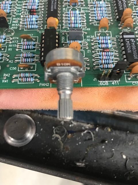
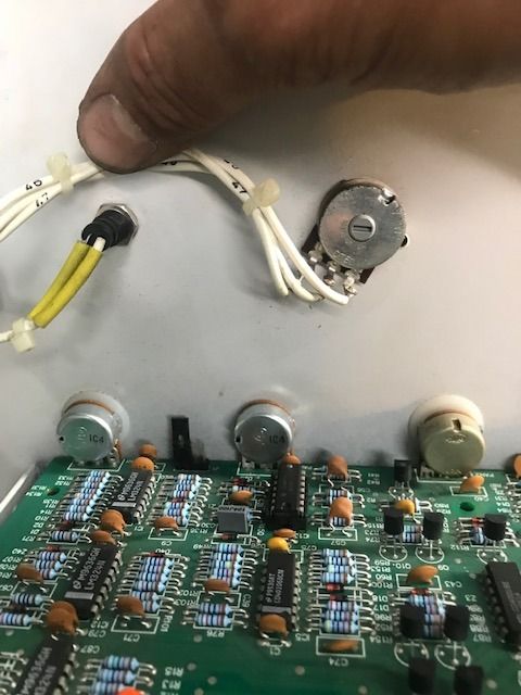
here are some photos and info for any other transtig 150 owners who want to do this modification to their own machine. for this modification you will need a small 10Kb linear potentiometer, a knob for the pot, front control panel will have to be removed and remove the PCB board by un clipping the plugs and plastic mounting tabs at the rear.
10Kb linear pot soldered into the empty spot "pan2", some fine solder work require
measure, mark out and drill a mounting hole for the pot
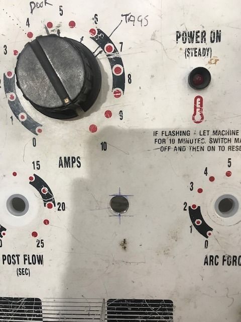
then re install the PCB into position with the pots mounted through the holes.

 Reply With Quote


Similar Threads
-
CIG Transtig 150
By GuzziJohn in forum WELDINGReplies: 41Last Post: 14th Sep 2020, 10:33 AM -
Aussie AL-960 owners or previous owners input please?
By befuddled in forum METALWORK GENERALReplies: 4Last Post: 6th Jun 2015, 10:14 PM -
Attention: Hare & Forbes BM30 owners and or clones
By eskimo in forum METALWORK GENERALReplies: 17Last Post: 17th May 2013, 09:16 AM -
DONE: Transtig 275
By Barterbuilt in forum METALWORK - Machinery, Equipment, MARKETReplies: 5Last Post: 2nd Apr 2013, 07:00 PM -
FS: Transtig 180
By ISL33P in forum METALWORK GENERALReplies: 8Last Post: 25th Jun 2007, 10:10 PM
